Reading RPLS is free for the whole profession. Members post, reply, and get the members-only rooms.


Notifications
Clear all

Topic starter
Translate
▼
English
Spanish
French
German
Italian
Portuguese
Russian
Chinese
Japanese
Korean
Arabic
Hindi
Dutch
Polish
Turkish
Vietnamese
Thai
Swedish
Danish
Finnish
Norwegian
Czech
Hungarian
Romanian
Greek
Hebrew
Indonesian
Malay
Ukrainian
Bulgarian
Croatian
Slovak
Slovenian
Serbian
Lithuanian
Latvian
Estonian
In https://surveyorconnect.com/community/threads/bench-mark-stability.332484&apos ;">another thread, we lamented the lack of good stability bench marks that aren??t too near an active railroad (unless you have the budget for a RR flagman), or on culverts and bridges near a stream with a lot of trees, and more trees when the RR line is abandoned and thus easier to access.
Marks mounted vertically on buildings are typically rated Stability B. A procedure to use them with GPS would improve the availability of stable points.
If you were to set up the GPS antenna in the clear, say 100 ft away from a building with a vertically placed disk, and use an automatic level set at the height of the mark, to set the ARP to the height of the mark, with equal sight distances, anyone should be able to match within a millimeter or so, well within the expected 2-4 cm accuracy of a 4-hour GPS session. The geoid isn't going to change significantly over a short distance.
It??s a lot of fiddling around to set up, but I would think this procedure would be less prone to blunders than any other leveling operation as no scale reading or calculation is involved. It avoids the error (if small) of depending on the zero point of a rod to transfer from the vertically mounted disk to a point on the ground, or the need for an assistant to hold a rod at the height of the vertical mark.
I'd like to try this method for my own checking purposes at a building about 3 miles from one of those culverts mentioned in the other thread.
However, if you tied an OPUS Share to the PID in the NGS system with a note saying it is an eccentric measurement of elevation, they probably wouldn??t like that. If you create a new point, they would never notice that it had an elevation relative to the PID.
Is there a way to make such a measurement useful to NGS?
Posted : November 12, 2017 9:04 pm

Translate
▼
English
Spanish
French
German
Italian
Portuguese
Russian
Chinese
Japanese
Korean
Arabic
Hindi
Dutch
Polish
Turkish
Vietnamese
Thai
Swedish
Danish
Finnish
Norwegian
Czech
Hungarian
Romanian
Greek
Hebrew
Indonesian
Malay
Ukrainian
Bulgarian
Croatian
Slovak
Slovenian
Serbian
Lithuanian
Latvian
Estonian
The way I do it is I setup a GPS nearby on a regular tripod with tribrach. I know the height of the ARP above the tribrach plate (0.033 m using a standard "hockey puck" adapter). Then I remove the GPS after the session, put the total station (S6) on, and shoot the benchmark cross reflectorless (D+R). The HI of the total station above the tribrach plate is also known (0.196 m). Simple math, accuracy of the transfer is about 1 mm assuming I know the heights to that accuracy, which I do, the 0.196 m is a design spec (matches old T2 height), and I measured the adapter with a micrometer.
Posted : November 12, 2017 9:16 pm

Translate
▼
English
Spanish
French
German
Italian
Portuguese
Russian
Chinese
Japanese
Korean
Arabic
Hindi
Dutch
Polish
Turkish
Vietnamese
Thai
Swedish
Danish
Finnish
Norwegian
Czech
Hungarian
Romanian
Greek
Hebrew
Indonesian
Malay
Ukrainian
Bulgarian
Croatian
Slovak
Slovenian
Serbian
Lithuanian
Latvian
Estonian
Locally, the best bench marks are the vertical monuments in the front face wall of Post Offices.
Posted : November 12, 2017 10:49 pm

Translate
▼
English
Spanish
French
German
Italian
Portuguese
Russian
Chinese
Japanese
Korean
Arabic
Hindi
Dutch
Polish
Turkish
Vietnamese
Thai
Swedish
Danish
Finnish
Norwegian
Czech
Hungarian
Romanian
Greek
Hebrew
Indonesian
Malay
Ukrainian
Bulgarian
Croatian
Slovak
Slovenian
Serbian
Lithuanian
Latvian
Estonian
How were these marks leveled orginally? Was there a jig or someting to get the bottom of the rod aligned on the mark?
SHG
Posted : November 13, 2017 12:08 am

Translate
▼
English
Spanish
French
German
Italian
Portuguese
Russian
Chinese
Japanese
Korean
Arabic
Hindi
Dutch
Polish
Turkish
Vietnamese
Thai
Swedish
Danish
Finnish
Norwegian
Czech
Hungarian
Romanian
Greek
Hebrew
Indonesian
Malay
Ukrainian
Bulgarian
Croatian
Slovak
Slovenian
Serbian
Lithuanian
Latvian
Estonian
If NGS OPUS made use the E/N of the DELTA H/E/N in the RINEX header, then you could probably set the E/N deltas as needed to account for this. But I don't think they use the E/N. Try taking one of your existing RINEX files, change the E/N values in the header and submit to OPUS (non-shared) to see if the computed mark position changes. I'll bet it doesn't.
Anywhere above the actual mark is acceptable, right? That's just the measured height above the mark. Perhaps you could create a tall Wile E. Coyote style jig extending up and out around roof overhangs and then back to vertical alignment with your antenna at the top. That jig could even be completely virtual. The antenna ARP just needs to be centered above the actual mark at a measured height and free of obstructions. How you get up there and over the mark is up to you.
Posted : November 13, 2017 3:59 am

Translate
▼
English
Spanish
French
German
Italian
Portuguese
Russian
Chinese
Japanese
Korean
Arabic
Hindi
Dutch
Polish
Turkish
Vietnamese
Thai
Swedish
Danish
Finnish
Norwegian
Czech
Hungarian
Romanian
Greek
Hebrew
Indonesian
Malay
Ukrainian
Bulgarian
Croatian
Slovak
Slovenian
Serbian
Lithuanian
Latvian
Estonian

Posted : November 13, 2017 6:21 am
Translate
▼
English
Spanish
French
German
Italian
Portuguese
Russian
Chinese
Japanese
Korean
Arabic
Hindi
Dutch
Polish
Turkish
Vietnamese
Thai
Swedish
Danish
Finnish
Norwegian
Czech
Hungarian
Romanian
Greek
Hebrew
Indonesian
Malay
Ukrainian
Bulgarian
Croatian
Slovak
Slovenian
Serbian
Lithuanian
Latvian
Estonian
When leveling, we have two methods to accurately level to vertical marks. We have a 50 cm invar strip that is easy to hold on a knife blade placed in the mark. More recently I bought a tripod with a hand crank (used for scanning) to raise and lower it. Easy to get the level at the exact height of the mark. I prefer method 1. We did a bluebook project last year that had several vertical marks, it was not easy to get the 0.000 reading into the submitted file.
Posted : November 13, 2017 7:38 am

Translate
▼
English
Spanish
French
German
Italian
Portuguese
Russian
Chinese
Japanese
Korean
Arabic
Hindi
Dutch
Polish
Turkish
Vietnamese
Thai
Swedish
Danish
Finnish
Norwegian
Czech
Hungarian
Romanian
Greek
Hebrew
Indonesian
Malay
Ukrainian
Bulgarian
Croatian
Slovak
Slovenian
Serbian
Lithuanian
Latvian
Estonian
Generally I just set a tape measure at them, you can burn a foot and tape them to the face of the building if you want. Of course you can set up a jig of some kind, many ways to do it, don't use the breather hole, it's a dimple but it's not the point. There are five of them that are regularly used in town, they all work well together.
Posted : November 13, 2017 9:01 am
Topic starter
Translate
▼
English
Spanish
French
German
Italian
Portuguese
Russian
Chinese
Japanese
Korean
Arabic
Hindi
Dutch
Polish
Turkish
Vietnamese
Thai
Swedish
Danish
Finnish
Norwegian
Czech
Hungarian
Romanian
Greek
Hebrew
Indonesian
Malay
Ukrainian
Bulgarian
Croatian
Slovak
Slovenian
Serbian
Lithuanian
Latvian
Estonian
Some good ways have been presented to use a vertically mounted disk in a leveling run, but not much has been said to solve the GPS on Bench Marks problem:
Bill93, post: 455218, member: 87 wrote: if you tied an OPUS Share to the PID in the NGS system with a note saying it is an eccentric measurement of elevation, they probably wouldn??t like that. If you create a new point, they would never notice that it had an elevation relative to the PID.
Is there a way to make such a measurement useful to NGS?
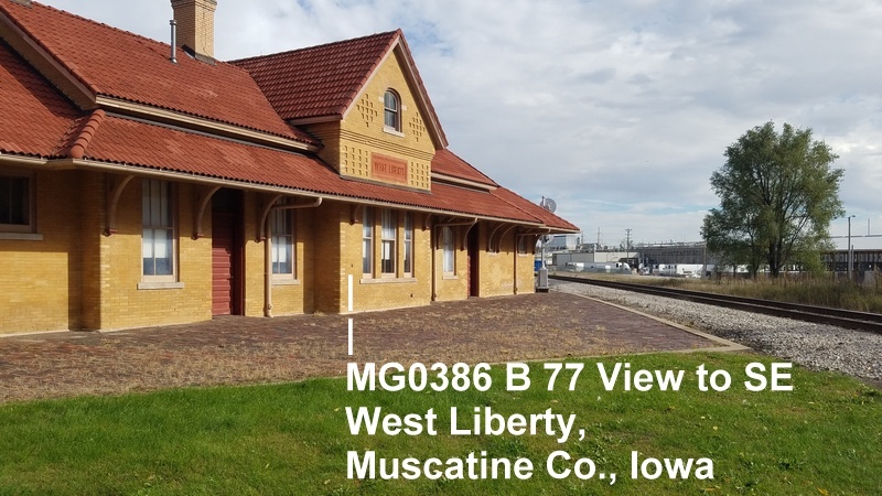
Astrodanco has a theoretical solution, but I'm afraid I won't be able to pull it off in practice.
astrodanco, post: 455243, member: 7558 wrote: create a tall Wile E. Coyote style jig extending up and out around roof overhangs and then back to vertical alignment with your antenna at the top.
Posted : November 13, 2017 10:04 am
Translate
▼
English
Spanish
French
German
Italian
Portuguese
Russian
Chinese
Japanese
Korean
Arabic
Hindi
Dutch
Polish
Turkish
Vietnamese
Thai
Swedish
Danish
Finnish
Norwegian
Czech
Hungarian
Romanian
Greek
Hebrew
Indonesian
Malay
Ukrainian
Bulgarian
Croatian
Slovak
Slovenian
Serbian
Lithuanian
Latvian
Estonian
For anyone not already familiar with it, please note that for GPS on benchmarks we do not deliver final processed results to NGS, we deliver an original unmolested RINEX data file containing the raw pseudorange, carrier phase, etc. measurements. Oh and they only process GPS, not GNSS.
Posted : November 13, 2017 10:08 am
Topic starter
Translate
▼
English
Spanish
French
German
Italian
Portuguese
Russian
Chinese
Japanese
Korean
Arabic
Hindi
Dutch
Polish
Turkish
Vietnamese
Thai
Swedish
Danish
Finnish
Norwegian
Czech
Hungarian
Romanian
Greek
Hebrew
Indonesian
Malay
Ukrainian
Bulgarian
Croatian
Slovak
Slovenian
Serbian
Lithuanian
Latvian
Estonian
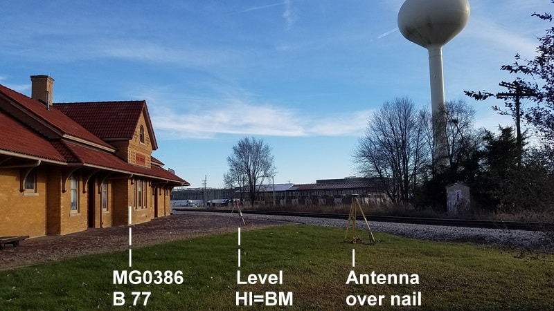
I tried my GPS setup method today for the vertically-mounted bench mark. This should be a more stable one than a post or culvert. Sky visibility should be workable, although not great. The roof is clay tile, not metal. We'll see later how the elevation comparison comes out, even though I don't think NGS will use it for GPS on BM.
Foresight distance = backsight distance = 26.5 ft.
Topcon auto level fine tweaked to HI = benchmark line.
GPS antenna set to same height, ARP Height=0.000 relative to BM.
Later, rechecked for settling with the level in two other positions.
Setup took way too long, but it was a very nice day for November. I picked what I thought was the best available (least bad) antenna position and taped and re-taped to put the level at equal sight distances. Found the antenna tripod couldn't go high enough. Moved to a closer position, not a whole lot worse visibility, and re-taped sight lines. Still not high enough, so had to swap tripods with the taller one under the antenna and the shorter one on the slightly higher brick-paved area for the level. Adjust legs, level the instrument. Check against bench mark. Readjust legs, repeat a lot of times. Final height adjustment with the tribrach screws. Repeat for antenna tripod height.
But despite all the fussy work, I'd bet my ARP height is as accurate as, and less likely to be blundered than, a measure-up.
Posted : November 20, 2017 8:15 pm
Topic starter
Translate
▼
English
Spanish
French
German
Italian
Portuguese
Russian
Chinese
Japanese
Korean
Arabic
Hindi
Dutch
Polish
Turkish
Vietnamese
Thai
Swedish
Danish
Finnish
Norwegian
Czech
Hungarian
Romanian
Greek
Hebrew
Indonesian
Malay
Ukrainian
Bulgarian
Croatian
Slovak
Slovenian
Serbian
Lithuanian
Latvian
Estonian
I should have replied earlier to this ...
astrodanco, post: 455243, member: 7558 wrote: If NGS OPUS made use the E/N of the DELTA H/E/N in the RINEX header, then you could probably set the E/N deltas as needed to account for this. But I don't think they use the E/N. Try taking one of your existing RINEX files, change the E/N values in the header and submit to OPUS (non-shared) to see if the computed mark position changes. I'll bet it doesn't.
I tried offsetting ANTENNA: DELTA H/E/N by 10 m north in the Rinex file and got identical results, so yes, they ignore it.
Posted : November 21, 2017 10:13 am
Topic starter
Translate
▼
English
Spanish
French
German
Italian
Portuguese
Russian
Chinese
Japanese
Korean
Arabic
Hindi
Dutch
Polish
Turkish
Vietnamese
Thai
Swedish
Danish
Finnish
Norwegian
Czech
Hungarian
Romanian
Greek
Hebrew
Indonesian
Malay
Ukrainian
Bulgarian
Croatian
Slovak
Slovenian
Serbian
Lithuanian
Latvian
Estonian
John Hamilton, post: 455258, member: 640 wrote: We did a bluebook project last year that had several vertical marks, it was not easy to get the 0.000 reading into the submitted file.
Seems as OPUS doesn't like a 0.000 height, either.
It pops up a screen saying to continue or to cancel. I continued and it used the non-zero value I had previously entered for a SESSION ON A DIFFERENT MARK. I had to add that value to the reported height to make a comparison to the BM.
Definitely not desirable behavior. Zero can be (is in this case) a valid entry.
I tried 0.0001 and it took that, and gave the same NAVD88 value I had computed above. Next time I'll try 0.00001
Posted : November 21, 2017 1:18 pm
Translate
▼
English
Spanish
French
German
Italian
Portuguese
Russian
Chinese
Japanese
Korean
Arabic
Hindi
Dutch
Polish
Turkish
Vietnamese
Thai
Swedish
Danish
Finnish
Norwegian
Czech
Hungarian
Romanian
Greek
Hebrew
Indonesian
Malay
Ukrainian
Bulgarian
Croatian
Slovak
Slovenian
Serbian
Lithuanian
Latvian
Estonian
That happened to me before when I had setup a profile in OPUS, it used the value in the profile. Not that it doesn't like 0.000, but it warns you in case you forgot to enter a value. I have repeatedly said I would like the option for it to use the antenna type and HI present in the rinex file.
Posted : November 21, 2017 1:38 pm
Topic starter
Translate
▼
English
Spanish
French
German
Italian
Portuguese
Russian
Chinese
Japanese
Korean
Arabic
Hindi
Dutch
Polish
Turkish
Vietnamese
Thai
Swedish
Danish
Finnish
Norwegian
Czech
Hungarian
Romanian
Greek
Hebrew
Indonesian
Malay
Ukrainian
Bulgarian
Croatian
Slovak
Slovenian
Serbian
Lithuanian
Latvian
Estonian
John Hamilton, post: 456754, member: 640 wrote: Not that it doesn't like 0.000,
I haven't figured out how to use 0.000. If I put it in my profile, would it take it?
That prior value that it used wasn't anything I had tried to put in the profile, just the last value I had submitted before this run. Does that automatically go into the profile without me asking it to?
Posted : November 21, 2017 4:05 pm
Translate
▼
English
Spanish
French
German
Italian
Portuguese
Russian
Chinese
Japanese
Korean
Arabic
Hindi
Dutch
Polish
Turkish
Vietnamese
Thai
Swedish
Danish
Finnish
Norwegian
Czech
Hungarian
Romanian
Greek
Hebrew
Indonesian
Malay
Ukrainian
Bulgarian
Croatian
Slovak
Slovenian
Serbian
Lithuanian
Latvian
Estonian
hmmm...not sure, I stopped using a profile when I found that it ALWAYS used that HI in the profile even if I put a different number in the box. Maybe they fixed that, I considered it a bug, others may consider it to be a feature 🙁
Posted : November 21, 2017 4:07 pm
Topic starter
Translate
▼
English
Spanish
French
German
Italian
Portuguese
Russian
Chinese
Japanese
Korean
Arabic
Hindi
Dutch
Polish
Turkish
Vietnamese
Thai
Swedish
Danish
Finnish
Norwegian
Czech
Hungarian
Romanian
Greek
Hebrew
Indonesian
Malay
Ukrainian
Bulgarian
Croatian
Slovak
Slovenian
Serbian
Lithuanian
Latvian
Estonian
They must have improved its behavior but didn't fix the 0.000 special case. When I bring up the submission page it fills in all the boxes per my last session, but uses anything I change, as you would want.
Posted : November 21, 2017 5:15 pm

Translate
▼
English
Spanish
French
German
Italian
Portuguese
Russian
Chinese
Japanese
Korean
Arabic
Hindi
Dutch
Polish
Turkish
Vietnamese
Thai
Swedish
Danish
Finnish
Norwegian
Czech
Hungarian
Romanian
Greek
Hebrew
Indonesian
Malay
Ukrainian
Bulgarian
Croatian
Slovak
Slovenian
Serbian
Lithuanian
Latvian
Estonian
re: 0.0 antenna height:
Sorry, OPUS sharing was trained to dislike unusual antenna heights; 0.0 should merely trigger a warning but for now it triggers the kill robot.
re: GPS on BM:
NGS is eager to find ways to facilitate gathering more GPS on bench mark data, perhaps by adding RTN observations, once we have a workflow established. There will be more outreach organized for that in spring 2018.
re: sharing eccentric occupations for vertically-set marks
Perhaps this is an exercise best done to test the existing geoid model; if you can get OPUS to provide a GEOID12B-based height which agrees with your offset plus the published BM height, then the model doesn't need any more inputs in that area. If you are off by a few cm or more, then ask the NGS regional advisor for advice.?ÿThere may be a few ways to fudge eccentric observations into the NGS database, but they may involve reset procedures, paperwork, leaving some type of recoverable eccentric mark behind, and ... shudder ... bluebooking. You could just say the eccentric observation was on the vertically-set mark, and update the scaled coordinates with (bad) eccentric ones, but I foresee problems getting past the sharing censors, and other devilishness if folks actually try to use or repeat your lat/lon results. </joe>
Posted : December 15, 2017 2:21 pm
Translate
▼
English
Spanish
French
German
Italian
Portuguese
Russian
Chinese
Japanese
Korean
Arabic
Hindi
Dutch
Polish
Turkish
Vietnamese
Thai
Swedish
Danish
Finnish
Norwegian
Czech
Hungarian
Romanian
Greek
Hebrew
Indonesian
Malay
Ukrainian
Bulgarian
Croatian
Slovak
Slovenian
Serbian
Lithuanian
Latvian
Estonian
I can remember when one very early version of Carlson would not handle 0, 90, 180 or 270 as an Azimuth direction when computing an intersection.
We had to insert an additional 0.0001 second to accommodate for this.
It was soon fixed as I hope this will.
Posted : December 15, 2017 5:44 pm
Topic starter
Translate
▼
English
Spanish
French
German
Italian
Portuguese
Russian
Chinese
Japanese
Korean
Arabic
Hindi
Dutch
Polish
Turkish
Vietnamese
Thai
Swedish
Danish
Finnish
Norwegian
Czech
Hungarian
Romanian
Greek
Hebrew
Indonesian
Malay
Ukrainian
Bulgarian
Croatian
Slovak
Slovenian
Serbian
Lithuanian
Latvian
Estonian
This measurement was done to check one on a culvert 3 miles away.?ÿ The culvert disk measured 44 mm low using Geoid12B versus the NAVD88 value on the data sheet.?ÿ The vertically mounted one measured 51 mm low.?ÿ?ÿ Comparing eight disks I have measured (not all shared), as listed in another thread, these were the furthest off the data sheet NAVD88 values.?ÿ Both are about 38 km away from the nearest station in the Geoid12B list, somewhat of a gap. Some of my measurements were very close using Geoid12B, indicating I didn't have a systematic problem with ARP heights.
https://surveyorconnect.com/community/gnss-geodesy/bench-mark-stability/paged/2/
Using xGeoid17B, they are of course far off the NAVD88 values, but all eight are consistently different from NAVD88 by amounts with a spread of only 17 mm.?ÿ My conclusion now is that the culvert measurement was pretty good, and Geoid12B is off a few cm in the gap between stations used to define it, but the GRAV-D data has fixed it in xGeoid17B.
So I got my check value, and it isn't super important to submit the session on the vertical disk.?ÿ I would still like to if it wouldn't cause any trouble, but it sounds like it might not fly.
Posted : December 16, 2017 12:15 am
Page 1 / 2
Next