Hi all,
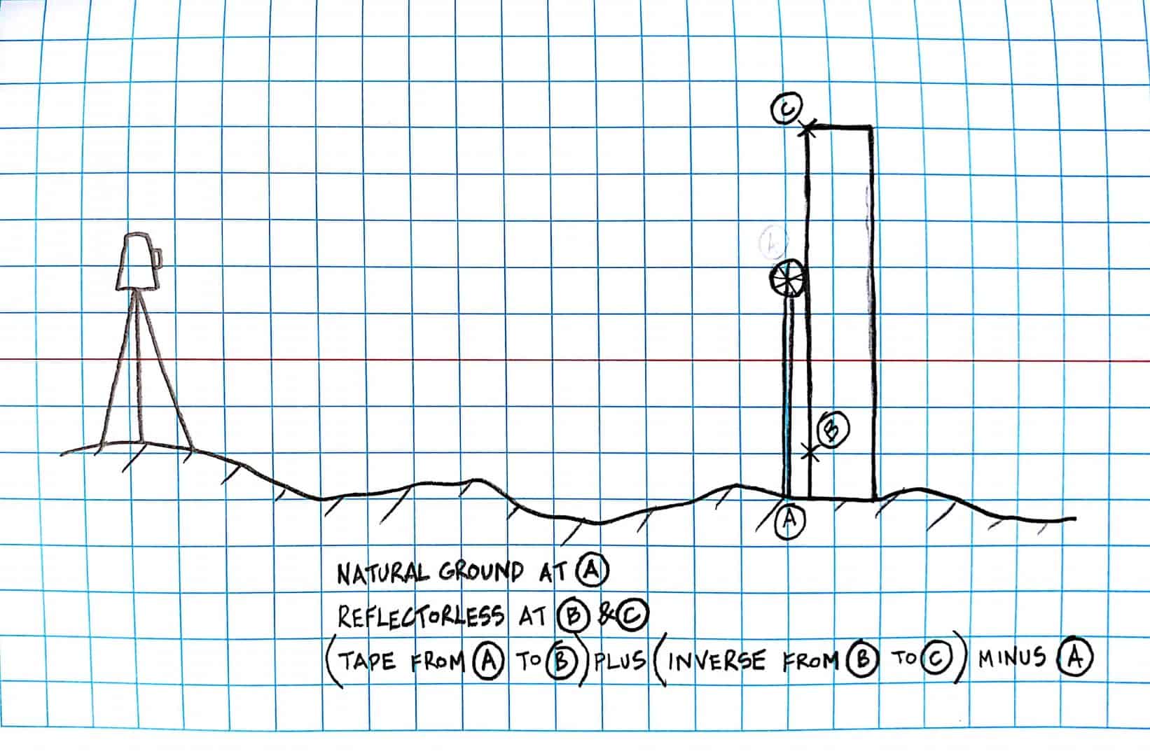
Can you throw out ideas for measuring as-built column heights using a total station. Laser scanning is one of the option i guess, but can we use reflective targets to measure the heights?
Thank you!
targetless. point at bottom, point at top, calculate the difference...
Hi Wayne well done on beating Bobby Charlton's record but your time is nearly up at Manchester United.
Why not use reflectorless?
Are they hot rolled steel, concrete or masonry? What are the accuracy requirements?
For steel I usually do a quick independent check using a Leica Disto from top of base plt to underside of top plt, useful when reflectorless shots are steep. Beware sighting the point at the top against a bright sky. Multiple shots to the top can help to confirm the measurement point, especially if you can view them in cross section in CAD. Reflectorless is always a bit uncertain but maybe that's just my ageing TS, newer ones have a narrower beam.
Artie Kay, post: 415687, member: 3428 wrote: Are they hot rolled steel, concrete or masonry? What are the accuracy requirements?
For steel I usually do a quick independent check using a Leica Disto from top of base plt to underside of top plt, useful when reflectorless shots are steep. Beware sighting the point at the top against a bright sky. Multiple shots to the top can help to confirm the measurement point, especially if you can view them in cross section in CAD. Reflectorless is always a bit uncertain but maybe that's just my ageing TS, newer ones have a narrower beam.
We have the Disto that has the cross hair view finder that we use to measure powerline clearances. The viewfinder really helps out in the sun.
Using an SMI data collector, shoot reflector less "Separate Distance and Angle" to the face of the column, record, then turn vertically to the base, record , then turn vertically to the top and record. After the first shot by moving the instrument vertically the rod height is zeroed and the angle recorded calculating the position and elevation for each subsequent shot. I have used it for stack heights and under eave elevations for roof heights.
Paul in PA
If they are steel, measure them when they are still on the truck. It is much easer that way ;). Jp
p.s. you might be surprised at the difference between plan and measured too!
I guess vertical angles from two control points is too simple.
Triangulation...double check with level rod or trig leveling random ones if possible.
I guess the question is how many columns. A dozen or a hundred?
Use a $99 Craftsman hand held laser measuring device.
Set it on the floor pointed up and click measure, voila!
(Only works if under 100 feet.)
like Larry said: multiple setups, multiple vertical angles... if "accuracy" is questioned you could run a 3D star*net analysis for those that demand some high tech solution for a simple problem.
Get a spotlight and measure the shadows...
Vertical angle from two control pts.
So you setup on a point shoot 'em all. Do that from a second point. Shoot 'em again. Then, assuming Hi and all, you have the elev of tops. Shoot the elevation at the bases.
But how tall are these, how many are there, are the tops obstructed so that you can only see a couple at a time. If they're 100 ft tall it's one thing, 20 ft tall shouldn't be that hard. A leveling rod with a hook on the top could work and read it with a level. Is it 0.01 or 0.1 accuracy?
When building pole barns, we would layout the pole locations, drill a hole there with an 3pt hitch behind a tractor to the limit, set in a power pole, set a 16d finishing nail near the bottom of each pole at the same elevation and tape measure to mark the cutoff at the top of each pole.
In that way, the floor of the barn retained a slope for drainage and the roof would fit the design and look right.
What is your client's intended use for the information?
If they are steel are they asking for plumb certification too?


