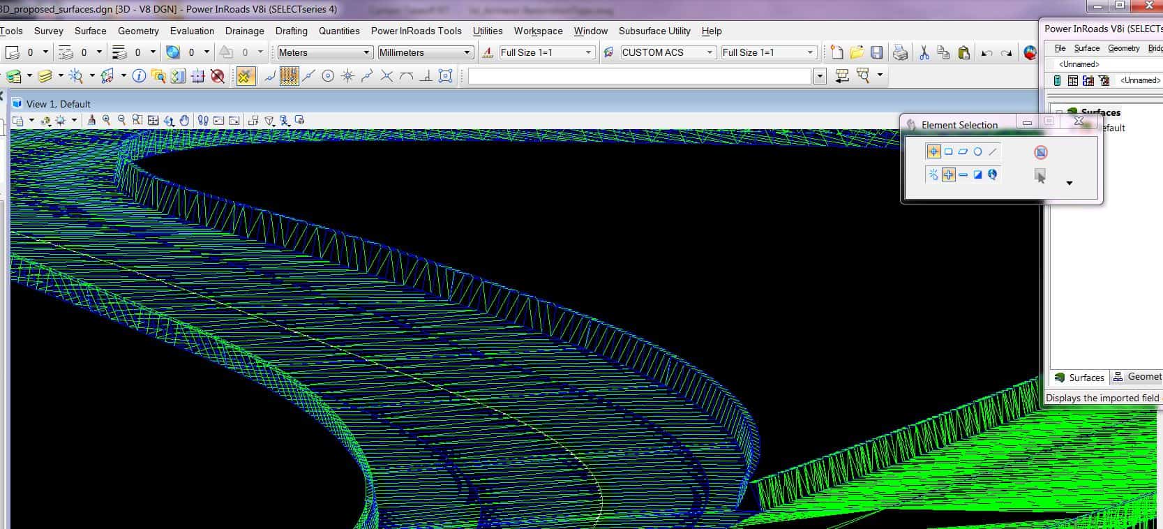
If you have two crossing corridors, then what do you do?
Make your corridor along a road that goes under a bridge.
Make another along a road over that bridge.
So there are surfaces at play that are on top of each other. The surfaces meet where the bridge touches the ground, so yeah... I could make two surfaces, which would help with the plan view for the bridge.
Thanks
For our state highway projects, we used to keep a daily mapping project for typical topography, and a bridge file for mapping between the expansion joints. Rule of thumb for them: if it can be lifted from the abutments or bearing plates, it goes in the 'bridge job'.
Topography is the main surface, and the bridge is processed separately.
Moe Shetty, post: 360574, member: 138 wrote: For our state highway projects, we used to keep a daily mapping project for typical topography, and a bridge file for mapping between the expansion joints. Rule of thumb for them: if it can be lifted from the abutments or bearing plates, it goes in the 'bridge job'.
Topography is the main surface, and the bridge is processed separately.
That's pretty much the way it's handled around here also. In the case of an overpass bridge, the approach, bridge seats and abutments are all part of the 'topo' surface. The bridge deck ( defined and separate from the abutment at the attachment joint) is a separate surface. I myself always lighten the lineweight and dash the linestyle of the contours on the structure in a drawing.
I make a "dirt" for the for my clients, which use withachine guidance in dozer or grader. Along with a bridge deck surfaces, if requested. But Not much need for a dozer on the bridge deck., or asphalt.
I'm working on one now where the roads cross at about a 60 degree skew off perpendicular. It's a real bear to get the subgrade models correct for dirt work with only 50' cross section to work from. I run the lower one thru with a wall on each side at the CL of bearing of the bridge that ties to the upper grade. They won't use the file to fill around the bridge ends anyway.
Eddy,
Build the 3d breaklines, then at the bridge approach along cut brraklins along scew angle. Create surface from breaklines.
Thanks all. Makes sense. Never had to worry about bridges before.
Sent from my SM-G900V using Tapatalk
I've only done surface drawings for two bridges. In one case, the area under the bridge wasn't a concern as it was in the water. In the other case, I built a second surface for just the bridge deck, starting at the expansion joints. The point where the deck surface met the main surface looked a little wonky if you zoomed in, but it worked for what we were doing.
The only time I have created a surface for the bridge deck is to generate layout with the camber properly accounted for between piers. This was a freeway overcrossing with horizontal and vertical curves, and superelevated, of course.


