Brad Ott, post: 456995, member: 197 wrote: ditto
ditto^2
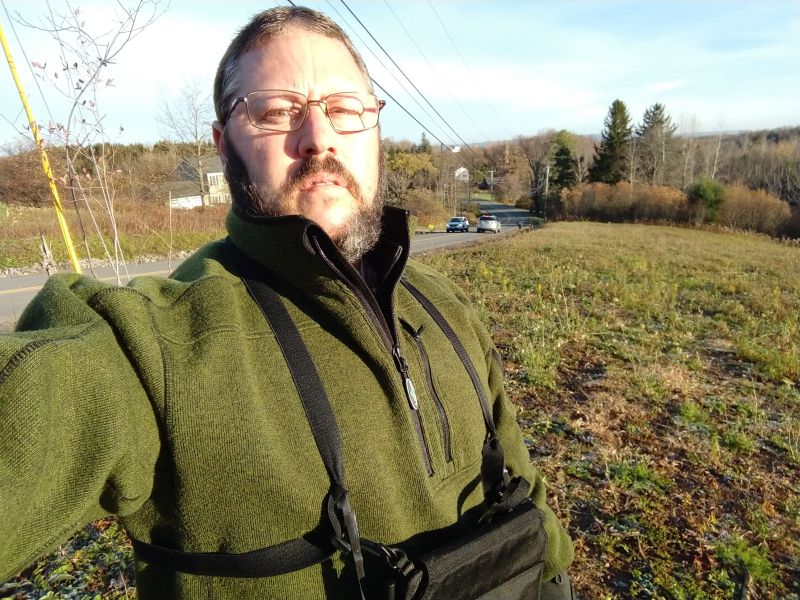
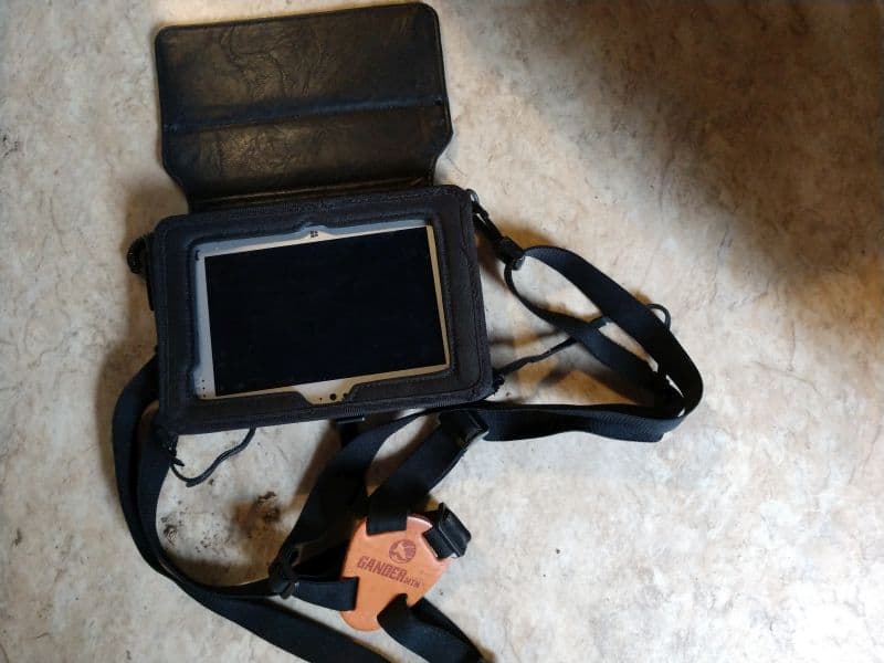
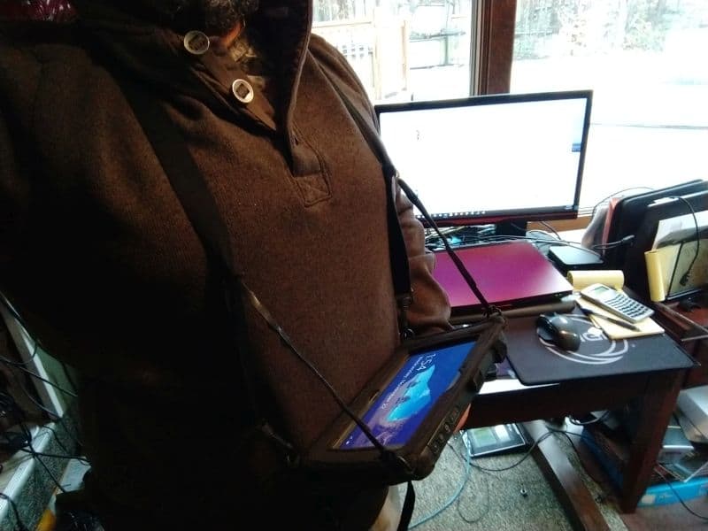
leegreen, post: 456948, member: 2332 wrote: Same here. I climb ladders, and scaffolding daily, along with brush. But I have gone to a chest mounted system for the controller. Similar to carrying binoculars.
Yes, have been looking for a harness similar to this. May I ask where one may purchase it from?
TIA
I want to be able to have field to finish automatically draw in the interior building corner based off of the shots provided. Ideally it would be a line from point 302 that is perpendicular to the building face located as points 300 & 301.?ÿ
I have messed around a little with the extend code but I can not get it to work without entering a dimension which I do not want to do. Any solutions??ÿ
Yeah I think it would be pretty bad on a tiny screen like that.?ÿ I used a Topcon FC 5000 tablet for a couple years and the giant screen made map view truly handy.
I never got around to doing it but it was on my list of things to tinker with in my spare time-- you can set the colors of the linework in the data collector so you aren't looking at a rat's nest of black lines.?ÿ I planned to set them to the same colors that Civil 3D drew them at but like I say I didn't quite get around to it.
I'm think there's a way to do this but I'm pretty sure you need a distance on at least one of the walls going to that corner.?ÿ The way you have it drawn up would be the fastest way to do it anyway since it would take about 5 seconds to finish the corner in cad.
You can do F2F in C3d, and that is what I recommend you start with. I also recommend doing your surfaces at the desktop. You can do these things in data collectors but it is just way easier to get them right in the controlled environment of the office. After you have a handle on that by all means, have a go at doing it in the field. Because you can't get them right in the office until the data is good, and complete.
This is how I would code my descriptions in the field for processing in C3D using the sample linework code set and having a figure prefix defined as "BLD." This uses the "X" code to eXtend the segment 300-301 by the taped distance into the corner (the extend distance can be negative as well for situations where you can project a building line from a corner that you can't see).
300 ... BLD.1
301 ... BLD.1 X(DIST 301 to ??) EXAMPLE BLD.1 X5.27
302 ... BLD.1
303 ... BLD.1
There is also the RT RightTurn code that allows you to shoot 2 points on a building line and then code the left/right legs to tape completely around the building using positive values for right turns and negative values for left turns.
Don't know how to do it automatically in C3D.?ÿ Your instrument man would to need tape it and/or taken notes.?ÿ Personally, I would have shot that in the reverse order (303, 302, 301, & then 300).?ÿ Much easier to tape from a defined corner to a defined corner.
Ie.
Pt # - Code
303, BLD1 B
302, BLD1 RT X-5 (assumption that the interior wall is 5 feet in depth)
301, BLD1
300, BLD1
?ÿ
Finish it off with a measured distance and the RECT command.
?ÿ
EDIT:?ÿ lil late to the party as Randy's solution is very similar.?ÿ That's what I get for grabbing a coffee.
^^^This^^^
Thank you for the example Randy. I was hoping there was a way to do this without a distance though. This is because many of the subdivisions of land in our area were created using building offsets, so we will go out on some jobs and locate the corners of 50+ buildings (as much as we can see per setup). This is just a pain for me to deal with and I was hoping for an easy solution to just slam in a perpendicular dimension from a point to a line for aesthetics.
Side note:?ÿ I found this vid quite helpful for surveying techniques when using C3D for F2F.
This is a very helpful video. Thank you
Piece of cake in my Belgian GeOpus
Have a look at codes PB and H
I have a new issue with my Field to Finish. I am trying to import data from my GPS unit as NAD83 State Plane Grid but it comes into the drawing ~12' off of the coordinates that are in my GPS unit. What setting could be causing this discrepancy? I have the survey database settings for field to finish on NAD83 grid as well so that does not appear to be the issue.?ÿ
Pretty good chance its a US survey foot and international survey foot problem.?ÿ The computer and the data collector setting should be the same in that regards.


