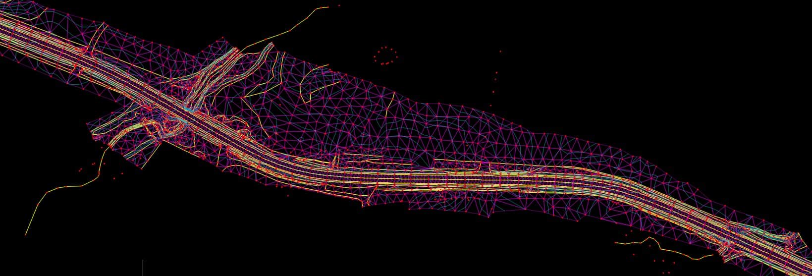
This shows some examples of swapping edges. Obviously this is a Civil 3D video but the concept is the same.
[MEDIA=youtube]rS6TOBTd20Q[/MEDIA]
Is a 3d polyline treated as a breakline by Carlson or do you need to tag it as a breakline?
Sent from my SAMSUNG-SM-N920A using Tapatalk
I have never tried without tagging the polyline. There is a option in field to finish that sets a "hard break line" there is also a option in the 3D data menu that allows the tagging of "hard break lines".
arctan(x), post: 443148, member: 6795 wrote: Is a 3d polyline treated as a breakline by Carlson or do you need to tag it as a breakline?
Sent from my SAMSUNG-SM-N920A using Tapatalk
In Carlson, I don't tag the breaklines. I just select them at the prompt "Select surface points and breaklines". I suspect tagging the breaklines simply means you won't have to select them on screen during the surface modelling procedure, as with tagging the "Inclusion and Exclusion Areas". So many of Carlson's routines have 2 or 3 different ways to achieve the same result.
I would set aside the topic of editing until you have mastered creation of surface models.
Yes, the heavy yellow lines were break lines.
In the CROSS SECTION view below, you can see a basic roadway prism. You don't want the triangles cutting off any of the grade breaks in the same way you didn't want the crown cut off in the first example. So you would string shots along the grade breaks and code them as being break lines and fill in between with ground shots. If the shoulder was a different grade as the pavement, you would add a break line along the edge of pavement.
In the cross section shown below, the grade breaks are not as well defined.
You could run some break lines where the yellow circles are shown, or maybe just saturate the top of the grade break and either side of it with ground shots.
You can see the area on the right side is really not well defined, so I would definitely just take additional shots there. So before I start gathering field measurements, I look the terrain over and pick out the major, well defined grade brakes. I chart my path out in my head, then start gathering those break lines. I code them BRK1, BRK2, ect. Then I go back in and fill in the areas between the break lines with ground shots.
A decision needs to be made as to which terrain features you need to show and which ones can be ignored. The final product of a topographical survey USED to be a contour map, and the accuracy needs related to the desired contour interval and the mapping scale.
Today, we can use the surface model for many different tasks, each perhaps with different accuracy requirements. Producing contours is just one of the ways a surface model can be used.
You might dive into this a little bit to understand how the software is deciding where to connect the shots.
https://en.wikibooks.org/wiki/Trigonometry/For_Enthusiasts/Delaunay_triangulation
cptdent, post: 442919, member: 527 wrote: As a cartographic drafter for 44 years, please allow me to tell you that smoothed contours are the desired end product. There's a little known item called a "carrying contour" ...../QUOTE]
Do you have any good examples handy as to how to properly show the "carrying contours", say where a bridge crosses a stream?
cptdent, post: 442919, member: 527 wrote: As a cartographic drafter for 44 years...There's a little known item called a "carrying contour"...
Do you have any good examples handy that show how to properly show say a bridge crossing a stream using a carrying contour? Wing walls are always difficult to show. I usually just trim out the contours in the vicinity of the wing wall and resume contouring the terrain. But then again, I have had no formal training.
cptdent, post: 443110, member: 527 wrote: Nope. Not in the world of cartography. In 1:50,00 scale mapping it is a flat line. In 1"=30' mapping it is a "u". "V"'s are the enemy of every carto editor and are not allowed on anything. Do you show a "v" on creeks? Surface material is totally irrelevant.
Yes, "V" shaped contours rarely accurately represent natural features, and the contour is an interpolated element with inherent errors. Smoothing the contour better represents natural terrain.
Here are some nice pointy contours to get your blood pressure up.They accurately depict the crown of a bridge deck.
Smoothing the contours would not be appropriate here (in my opinion). If I were to as-built the concrete, I also would not smooth the contour at the crown either.
something else to keep in mind- https://pubs.usgs.gov/fs/1999/0171/report.pdf
"The vertical accuracy
standard requires that the elevation of 90
percent of all points tested must be
correct within half of the contour interval.
On a map with a contour interval of
10 feet, the map must correctly show 90
percent of all points tested within 5 feet
(1.5 meters) of the actual elevation."
ease, post: 443273, member: 1584 wrote: As respectfully as possible, I see about 20 triangles I would flip in that tin...
No doubt and no offense taken. I can go back to every tin that I have made and find areas that look like I could have done something differently.
That goes for ALL the work I have ever done really - it's never perfect.
I'm just not that big on editing the TIN (assuming care was taken in the field).
I have used surface models for larger earth moving projects and when I stake OG from a surface model, it's amazingly accurate. There are times that you KNOW something is not right and of course you have to try and fix it.
One additional thing about break lines...they should not cross each other.
imaudigger, post: 443261, member: 7286 wrote: Yes, "V" shaped contours rarely accurately represent natural features, and the contour is an interpolated element with inherent errors. Smoothing the contour better represents natural terrain.
Here are some nice pointy contours to get your blood pressure up.They accurately depict the crown of a bridge deck.
Smoothing the contours would not be appropriate here (in my opinion). If I were to as-built the concrete, I also would not smooth the contour at the crown either.
Is this a plan view of an overpass? Why do the contours go out past the "edge of bridge deck? They're bridge deck contours aren't they? Finally, what do the x's represent at the top of the drawing?
imaudigger, post: 443283, member: 7286 wrote: One additional thing about break lines...they should not cross each other.
but in the event they do, it needs to be on purpose, at a common point with a good elevation. ie. at the back of sidewalk in a laydown at the edge of an asphalt pavement driveway. Technically these are crossing chains/ but the principle is the same.
rfc, post: 443294, member: 8882 wrote: Is this a plan view of an overpass? Why do the contours go out past the "edge of bridge deck? They're bridge deck contours aren't they? Finally, what do the x's represent at the top of the drawing?
That is a plan view of a cast in place slab bridge with wing walls (over a stream). The contractor and or their engineer will be expected to lay a scale stick on the plan sheet and determine the concrete grades at any location of their choosing. They will finish the concrete using a piece of equipment that runs on rails which are located on false work that extends beyond the structure.The contours will be used to develop a false work plan which includes camber strips to account for deflection under dead/live loads and settlement. Having the contours and station references extend beyond the structure just makes that easier.
There is a note on that plan sheet that states that the "X" is a 10' station interval along the "A" line.
If you were tasked with scaling some elevations...it would probably make better sense.
You can see there is a little bit of super elevation change occurring on that lower lane.
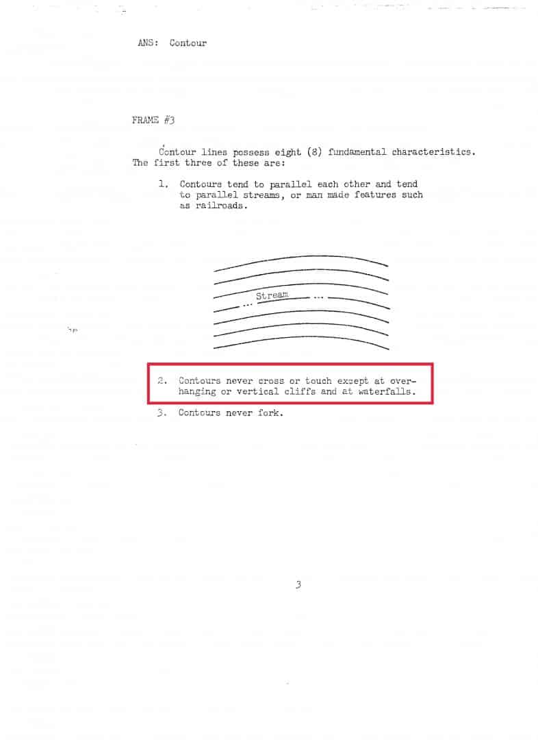
Cameron Watson PLS, post: 443113, member: 11407 wrote: I think he was referring to "Page 6" in terms of the PDF in total, not page 6 in terms of the numbering scheme of the document. In all fairness the document does say they can cross in limited circumstances but I have not combed through it in detail to see if addresses those circumstances further by introducing the concept of "carrying contours".
You need a copy of TM-23A or TM S-1 to get the specifications on carrying contours.
One thing is clear: I need additional well placed shots, which I'll proceed to take.
But it got me wondering:
How many topo shots/hour can you do with a robot? Commercially speaking, I'd think doing hi-res topo for a client has got to be up there in cost, compared to other surveying tasks.
rfc, post: 443349, member: 8882 wrote: One thing is clear: I need additional well placed shots, which I'll proceed to take.
But it got me wondering:
How many topo shots/hour can you do with a robot? Commercially speaking, I'd think doing hi-res topo for a client has got to be up there in cost, compared to other surveying tasks.
Now you're on the right track. This is why breaklines are so important. Collecting breaklines results in efficiency. ie less grid shots are required in areas of consistent slope. Additionally, if you collect all linear features in 3D you can use those as breaklines in your surface model. My feature codes include lines for edge of pavement, cl road, top of slope, toe of slope, back of curb, fence, etc. Once all of your linear features are collected (breaklines), then you can fill in with spot shots where needed.
Sent from my iPhone using Tapatalk
BushAxe, post: 443353, member: 11897 wrote: Now you're on the right track. This is why breaklines are so important. Collecting breaklines results in efficiency. ie less grid shots are required in areas of consistent slope. Additionally, if you collect all linear features in 3D you can use those as breaklines in your surface model. My feature codes include lines for edge of pavement, cl road, top of slope, toe of slope, back of curb, fence, etc. Once all of your linear features are collected (breaklines), then you can fill in with spot shots where needed.
Sent from my iPhone using Tapatalk
Thank you for that. If I understand correctly, it might be more useful to take shots ALONG the bottom of a ditch or ravine, the top edges of same, such that the string of shots might form the basis of breaklines, rather than multiple "traverses" across the feature (like multiple cross sections of the ditch, the road, the ditch on the other side, etc.
But you didn't answer the question 😉
How many shots an hour is typical with one man and a robot?


