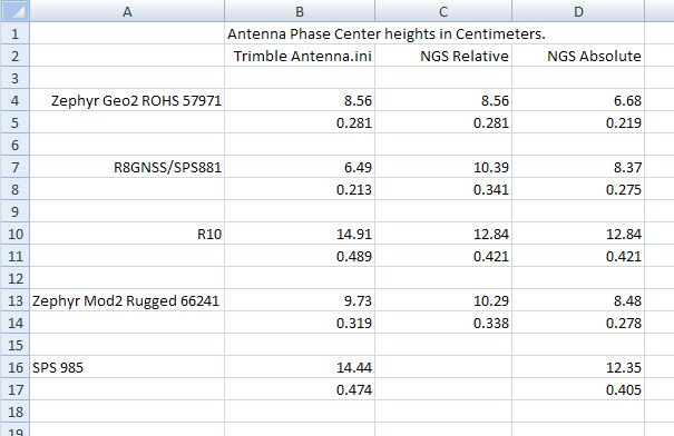
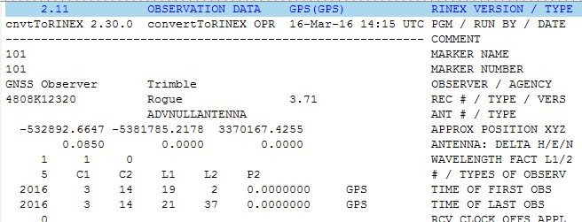
About a year ago, I was trying to work thru a similar issue and had looked up the APC heights from different sources. At the time I was learning static processing and opus projects. These are receivers / antennas that I had access to. Then I had to give up the two R10's to another jobsite and never took it any further. The thing I noticed is the trimble file matched the NGS Relative on some and not on others. The NGS Relative matched the NGS Absolute on some and not on others. The trimble file was less than the NGS Absolute on one and more on the others. There was an issue with the Zephyr Rugged that I wasn't sure I was looking up the same antenna in each file.
Keep in mind that I am still new at antenna files and I was never able to finish my research to the point of convincing myself I was correct so take it with a grain a salt. I wish Trimble would abandon their files and go with absolute values on everything.
James
The latest (07/03/2017) Antenna Calibration File (ngs14_1949.atx) has the following data for the Trimble R-10 (Readers Digest Version). I'm pretty sure that THIS is the File used by OPUS.
TRMR10 NONE TYPE / SERIAL NO
ROBOT Geo++ GmbH 5 14-MAR-13 METH / BY / # / DATE
5.0 DAZI
0.0 90.0 5.0 ZEN1 / ZEN2 / DZEN
4 # OF FREQUENCIES
IGS14_1935 SINEX CODE
# Number of Calibrated Antennas GPS: 005 COMMENT
# Number of Individual Calibrations GPS: 010 COMMENT
# Number of Calibrated Antennas GLO: 005 COMMENT
# Number of Individual Calibrations GLO: 010 COMMENT
# GLONASS PCV COMMENT
# derived from Delta PCV per 25.0 MHz COMMENT
# for frequency channel number k=0 COMMENT
G01 START OF FREQUENCY
-0.91 -0.65 +128.36 NORTH / EAST / UP
G02 START OF FREQUENCY
-2.68 -6.43 +119.69 NORTH / EAST / UP
R01 START OF FREQUENCY
-0.91 -0.65 +128.36 NORTH / EAST / UP
R02 START OF FREQUENCY
-2.68 -6.43 +119.69 NORTH / EAST / UP
You can (I hope) download the entire (zip) File below:
Loyal
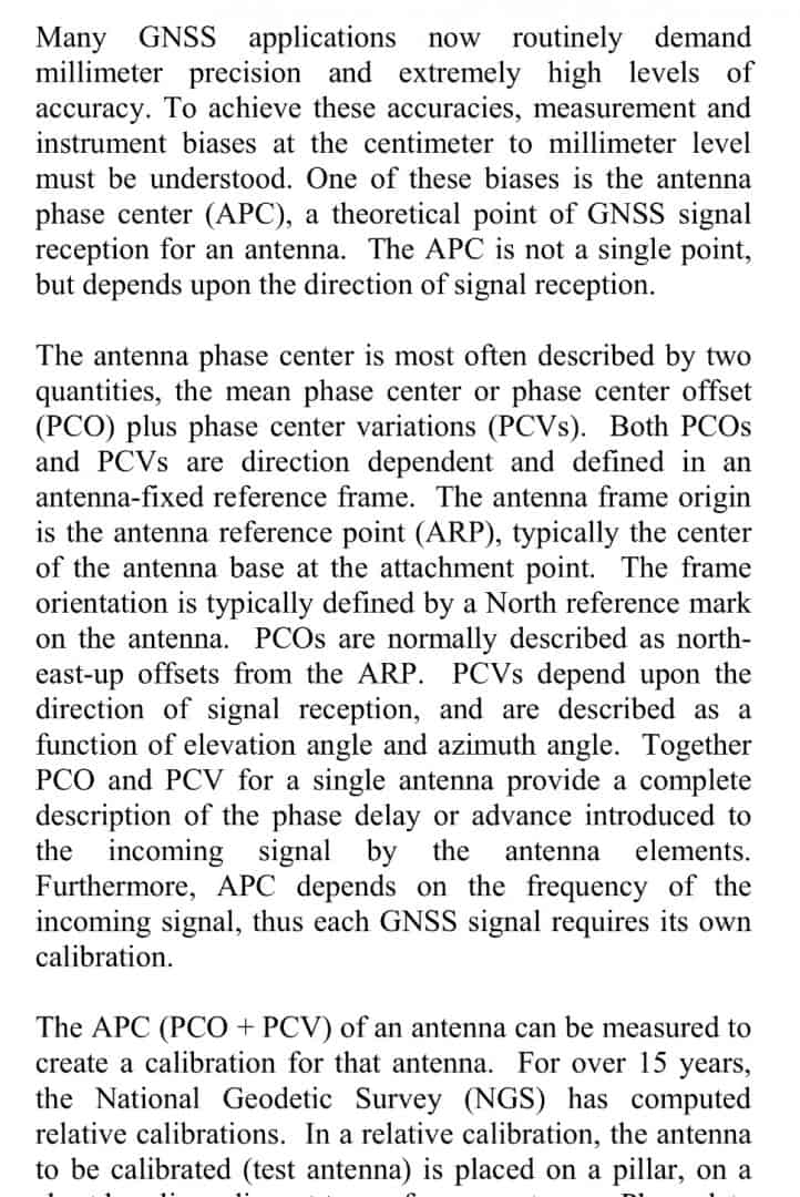
This is extracted from an excellent article on absolute antenna calibrations found here: https://geodesy.noaa.gov/CORS/Articles/Bilich-and-Vader_ION2010.pdf
Note as well that the article mentions that while a number of specific antenna models are calibrated there possibility of variations from the antennas tested.
As an aside, I recollect in the early 2000s that one manufacturer had added/changed some internal heat shielding without notification. This required identifying when the change took place, determining the specific antennas impacted and reprocessing data observed with these units. Hopefully the communication issue has been resolved. Also in conversations with those performing the first relative tests it was found that some manufacturers had significant quality control problems with large differences between individual antennas.
Not up-to-date on the commercial processors. I do not know whether they use both the PCO and PCV values.
HTH,
DMM
As Rodney King said once...Can't we all just get along? I think this issue cries out for standardization. I would think the IGS would be the one to make definitive antenna models that everyone can use and we would all be on the same page, so to speak. Having Trimble do their models, and NGS their, and who knows how many others just leads to confusion.
I don't disagree, but Trimble has to do their own - when they roll out a new product the model has to be in TBC and Access for us to be able to use it, they can't wait for third party testing. Of course they can (and I'm sure do) make Beta units available to NGS and other agencies prior to release, but still...
Lee: I get that. But I am distressed to see these differences. Not just absolute differences, but relative differences. If one consistently uses a certain model, then the absolute differences between models don't matter. But when one model has a difference between two antennas of 8.42 cm and the other model has a difference of 2.45 cm (JaRo table above for R8 and R10, Trimble vs NGS), then that is VERY concerning.
From my limited knowledge, Geo++ is the leader in determining phase center variations.
John Hamilton, post: 438522, member: 640 wrote: But when one model has a difference between two antennas of 8.42 cm and the other model has a difference of 2.45 cm (JaRo table above for R8 and R10, Trimble vs NGS), then that is VERY concerning.
Last year when I was working on this, one of the last things I did was run the R8/SPS881, Zephyr 57971, and R10 thru GNSS Solutions using the absolute antenna values and got 0.004m difference. Loyal did the same thing thru his software with my files and got 0.011m. This was three all-thread rods clamped to three pipe post about 8 foot apart (typical fence corner brace post) with a jam nut precisely set with a B1 level at the same elevation on each post.
I am convinced that the Absolute values are correct. I am not convinced that OPUS uses the absolute values on every file sent because of the way the rinex converter jacks with the file. My next goal was to make an antenna.ini file with the absolute values and use it instead of the trimble file. I never got that far.
I am also convinced that the R8/SPS881 needs about 0.08 ft added to the rod height to have the slightest chance of being right or close when using the trimble antenna file in the DC. It is in my RTK survey style now and will stay there until I get a better antenna file in my DC.
Quite frankly, I never would have gotten anywhere if it hadn't been for Loyal guiding me thru it. This board ROCKS!
James
I wish this would have come up a few months ago, this seems like something FIG should undertake as a standardization project. The next FIG Congress is in Istanbul in May of 2018. I hope things settle down there by then.
To me, it doesn't matter who does it, just that one entity should be responsible. In my opinion it should be IGS. Not that they necessarily need to do all the tests, but they could maintain the database. As for Lee's comment about a manufacturer needing to get a new model out, that could be accomplished (for a fee) in a timely manner I would think. Or maybe the manufacturer could do their own following a rigorous set of specs so that it would be compatible no matter who does it.
John Hamilton, post: 438513, member: 640 wrote: As Rodney King said once...Can't we all just get along? I think this issue cries out for standardization. I would think the IGS would be the one to make definitive antenna models that everyone can use and we would all be on the same page, so to speak. Having Trimble do their models, and NGS their, and who knows how many others just leads to confusion.
The point of my earlier post was to empathize the need for both PCO and PCV values in the calibration. Discussion seemed to be centered on the offsets only. The absolute calibrations not only include vertical angle PCV values but also those for azimuth. Do the manufacturer models include the azimuth-related values?
As for the comment about the need for IGS to be the lead on this issue. They are.
The first image is from:
http://www.igs.org/wg
The lsecond from the NGS Antenna Calibration FAQ.
I noticed the link in my earlier post did not work. Here is another try...
https://geodesy.noaa.gov/CORS/Articles/Bilich-and-Mader_ION2010.pdf
Both NGS and IGS publish Antenna definition files and have for many years now. NGS_ABS.PCV and IGS08.ATX for instance. These are the standard bearers. Why can't Trimble use these antenna definition files in lieu of their own when present? Why does everyone have to be different.
My comment was not intended to downplay the significance or the concerns about what you're finding. I've never noticed it but now that you've pointed it out I'm going to pay a lot closer attention.
Being an OPUS issue (Trimble seems to have no problems handling the antenna measure points) with the R10, it brings up the question just how many other antenna types have similar issues. I suspect there is little real world testing going on. It's one thing to measure to the wrong point on the antenna when you submit to OPUS, it's a whole nuther to have the right point be wrong.
Mighty Moe: I disagree about it not being a Trimble problem. The way i started seeing all of this was on Trimble RTX submittals.
I wonder whether any of the users of OPUS-Projects have noticed an issue when mixing these antennas? As the tool uses the OPUS processor and large projects likely involve different antennas, I would expect this problem would have emerged.
Has anyone using OPUS-Projects with mixed antennas has looked at this? If no bias is evident, perhaps (as the Bilich/Mader paper notes) Mr Hamilton's problem is unique to his antenna requiring an individual calibration?
GeeOddMike, post: 438723, member: 677 wrote: I wonder whether any of the users of OPUS-Projects have noticed an issue when mixing these antennas? As the tool uses the OPUS processor and large projects likely involve different antennas, I would expect this problem would have emerged.
Has anyone using OPUS-Projects with mixed antennas has looked at this? If no bias is evident, perhaps (as the Bilich/Mader paper notes) Mr Hamilton's problem is unique to his antenna requiring an individual calibration?
Unless a given station is occupied with DIFFERENT receivers (types), any variance in antenna calibrations would not [necessarily] show up in an OPUS_Projects solution (unless maybe when high order BMs are involved). The last OPUS_Projects job I worked on DID however indicate a NON-trivial variance between my two NOV-503 Choke Rings, and my buddy's two R8_Model_3's. In as much as he was going to continue the project using his R8-3's, I "fudged" the NOV_503 "HIs" to match the R8_3 heights. In this case, several Bench Marks were observed several times by BOTH Antenna Types, and the height variance was very consistent (about 3 centimeters as I recall).
We have had a PLAN where we would simultaneously run half a dozen antenna types on Mark Silver's "Horizontal Bar" next to a PBO Station, but haven't been able to get everyone involved together yet (it will take a full day to pull off, and be a 300 mile round trip for me).
Loyal
I have a large OPUS-Projects network that contains mixed R10 and R8 data; what I don't have at the moment is time to figure out what points / occupations have common data sets and compare them. And there's so much deviation in the vertical of the CORS stations around Houston that a few centimeters could be hard to spot.
When I have time I'll try to re-submit some sessions and I'll make sure that all the solutions come from the same three CORS.
John Hamilton, post: 438720, member: 640 wrote: Mighty Moe: I disagree about it not being a Trimble problem. The way i started seeing all of this was on Trimble RTX submittals.
I will keep looking, my RTX for the two receivers were very close, and when I processed against the near CORS using TBC as a processor they were almost identical, I will process the two solutions using the three CORS OPUS used and see what Trimble comes up with.
If this is just a Trimble measure issue, it is simple to check with mixed receivers and close points, short occupation times. Points that can be leveled.
I am open to the possibility that somewhere along the line Trimble changed the R10 and that is why the mismatch is appearing. Doubtful, but a possibility.


