I've used Trimble for years but now I have Leica equipment to work with.
I'm trying to use SPC scaled up to ground. With Trimble I tell the DC to use NAD83, Nebraska 2600 zone, and input my scale factor...and I'm off and surveying with ground coords.
I've been trying for a few months to figure out how to do this with Leica either in VIVA or LGO. I've read all the user manuals and have searched all over the internet without coming up with any info.
If anyone could point me in the right direction it would really be appreciated.
Here is how I did it with Trimble Survey Controller. (scale factor would 1.0003828 or something similar not 1.000000)
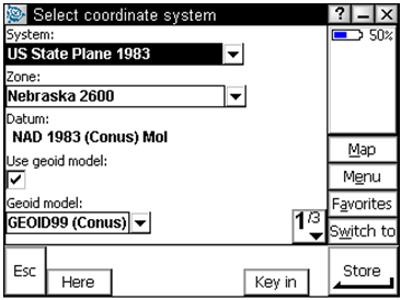
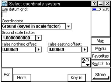
Just scale it back to grid and go to work. Mixing and matching is a bad idea. I've never attempted to survey on the surface and grid at the same time.
"I've used Trimble for years but now I have Leica equipment to work with."
I feel your pain...however staying on grid or ground with whatever map projection you are using is as easy in Viva as Trimble.
When you set up New Job for TPS there are are series of tabs at the top of your screen. Go through each to see what they are but you will see "Coord System" tab where you pick your coordinate system (State Plane, custom LDP, etc.) or None.
Then go to next tab which is "TPS Scale." If you have no coordinate system defined and just want to scale up or down pick "SF/GeoPPM" enter you scale factor below. If you are working in a defined system pick "Stn & coord system" and then TPS will calc a combined scale factor based on your chosen projection at each new set up.
Eezy Peezy. We work in SPCS all the time and this is how we stay on SPCS with TPS.
Leica gurus may have other ways.

Thanks for the replies.
I should of mentioned this is for GPS not TPS.
I don't want to mix grid and ground. I used Trimble when working for the Dept. of Roads. Everything was done on the ground with "modified" SPC. It always worked great and was real easy to get back to SPC if someone requested it.
My current method with Leica is to set control with SPC scale them up to ground and then do a site calibration to get a "modified" SPC system. It works but I thought there should be an easier way than having to start off at square one with each new project.
I've been reading up on LDP's they seem like they might be a better method than modified SPC...still have some more studying to do though.
No worries. Just create a projection in your library (either in the DC or LGO) with the SPC "at ground" scale factor. That's all you are doing by going through "localization" process each time. Personally I would stay SPC in the field and then if you need to go to ground do it in the office only for whatever internal or external clients want your "bastardized" SPC at ground.
In Trimble world if I decided to do a SPC at ground system for whatever reason I would do it in TGO/TBC and then upload the DC/Job file right to the data collector. That way the GPS system would be working in the same system. LGO is similar but would take too long to type.
I still miss yellow but green does all the same stuff if you can find where they hide it or what they call something. YMMV...
I don't want to mix grid and ground. I used Trimble when working for the Dept. of Roads. Everything was done on the ground with "modified" SPC. It always worked great and was real easy to get back to SPC if someone requested it.
My current method with Leica is to set control with SPC scale them up to ground and then do a site calibration to get a "modified" SPC system. It works but I thought there should be an easier way than having to start off at square one with each new project.
I went through the same process with Leica and a client of mine. I thought I could show him how to set it up in his software and we got on the phone for hours with a Leica rep. Turns out it was easier to "localize" to existing control, however, unlike Trimble I couldn't "localize" in the office, he had to go to the field which was even more of a pain. It was like they didn't know what I was talking about when, I said; "we'll sit here and input the localization"
It was an older version and that's probably why we couldn't get it to do what I wanted.
I tried this Lambert one parameter projection and it didn't work.
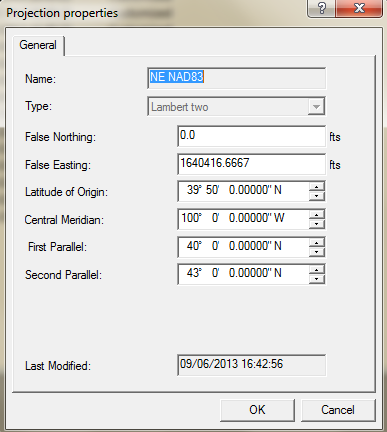
I used the parameters from NE NAD83, but the NE NAD83 projection is a Lambert Two parameter projection but Leica doesn't give you the option to enter a scale factor for a Lambert Two.
I have to admit I'm still trying wrap my head around projections.
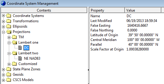
I also talked to my Leica rep in the past and he didn't seem to really understand what I was trying to do. He did call Leica tech support and their only suggestion was to use COGO to scale up my points after I shot them.
The difference is either a Planar or Secant projection. In Texas it is defined by statute and specifies the paramters. Check to see if your "two" mathces Nebraska's definition for that zone.
It matches the statute for the Nebraska zone.
I guess I need to read up and figure out what the difference is between the different Lambert projections.
Here is what I have for my NE NAD83 projection.
Have you tried the customized option?
It might allow you to enter all the info as if it was a Lambert projection and also the scale factor you want.
You were on the right track, but with the wrong values
Unless there is "hidden" tool that is similar to what you used on the TrimStuff, you were on the right track when you tried the single-parallel Lambert option in your Leica software - you just need to enter the correct parameters as shown following:

Leica terminology for the various parameters appears to be a bit different than that shown here, but you should be able to sort it out without difficulty. Post a screen snap of the dialog where you enter the parameters if you have any trouble figuring out what goes where.
Here my test point with PID LJ0230 is down in Dundy county near the Nebraska - Kansas - Colorado point. The test point with PID NM1743 is up in Dixon county north of Newcastle in far northeast Nebraska. These widespread points were chosen to give a chance for rounding errors to reveal themselves.
The latitudes, longitudes, statutory northings, and statutory eastings are all from the NGS datasheets. The scaled northings and scaled eastings are the NGS values multipled by the "Ground Scale Factor" in the original post.
The northings and eastings for the test points are in U.S. Survey feet.
I tested both the statutory and scaled projection parameters by establishing one-parallel Lambert projections in Trimble Survey Controller, but any similar program would work fine. My worst difference between what I got in SC and the scaled values shown above was 0.006 ft, which should be acceptable considering that NGS only publishes Nebraska SPCs to 0.01 ft. And it will be a heck of a lot better than you would ever get by throwing in a bunch of field measurements.
For clarity, the values shown as "statutory" are what people seem to like to call "grid", the straight SPCs from a projection as defined by statute. The "scaled" values are what get called "ground" or "surface" or "modified", somehow glossing over the fact that they are also on a grid, but a grid that is (usually) somewhat close to the ground surface.
Do a web search for "NOS NGS 5" and you will find PDFs of the NGS document that has the parameters. The parameters for Nebraska are on page 98 of that document.
If you want the Excel workbook I made to do the scaling shown above, send me an e-mail via the link by my name and I can send it as an attachment. Or we can make other arrangements if that does not work on your end.
I will resist any snide comments about the Leica organization's support capabilities:whistle: Since there are many agencies other than the Nebraska Department of Roads using this simple-but-much-criticized scaling method it sure seems Leica should provide an easy way to work with those who are calling the tune.
GB
You were on the right track, but with the wrong values
Thank you Glenn.
Just a couple of questions to make sure I'm looking at this correctly if you don't mind.
From NOS NGS 5 you get the coefficient for grid scale factor of 0.999658 you then multiply that by the reciprocal of your CSF to get your 1.000041?
When using the Lambert one parallel projection I need the central parallel instead of the first and second parallels?
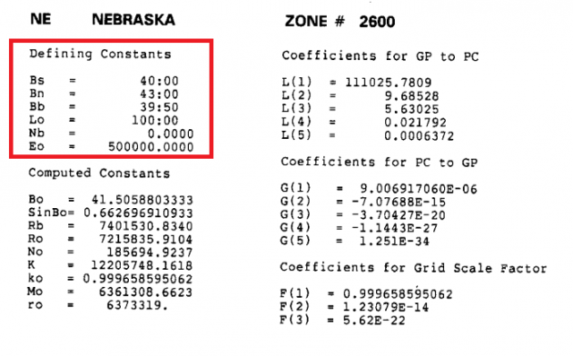
I don't understand the difference of false northings and eastings. I thought it was 0.00/500000. I do see in NGS 5 where it shows the Eo and No that you have.
Thanks again for your help.
You were on the right track, but with the wrong parameters
Needed to adjust the subject line - don't want to sound like I am criticizing your values!
The most-common two-parallel Lambert conic projection has unity (1.000000) scale factor at both parallels, which means the cone is secant to the ellipsoid.
What we do here with the one-parallel Lambert conic is to set the scale factor less than one at the central parallel (latitude of origin) so we end up with the same secant cone that intersects the ellipsoid just like (and at prezactly the same latitudes as) the equivalent two-parallel definition.
Since you want to move the cone up to your approximate elevation (which is above the ellipsoid), you do as per your suggestion and the earlier example and multiply the scale factor in the statutory projection definition by the inverse of the CSF. When the scale factor is then greater than unity the cone is up above the ellipsoid. (To state the obvious, if the scale factor was unity at the central parallel then the cone would be tangent to the ellipsoid.)
With the typical two-parallel Lambert the grid origin (where the false northing and false easting exist) is defined someplace south of the area the projection is intended to cover.
For the one-parallel Lambert the grid origin is at the intersection of the central parallel (origin latitude) and the central meridian (origin longitude). To match the northings of the two-parallel projection the false northing is not the simple 0.000. If one was not constrained to match the two-parallel numbers the false northing could be anything and would undoubtedly be a nice round number large enough so northings were still positive at the Kansas line.
Apparently some software uses the same dialog for both one- and two-parallel Lambert projections. I found a post from SurveyorConnect participant mkennedy on an ESRI forum that stated that in ArcGIS you enter the same value for both parallels and the latitude of origin, along with an appropriate scale factor.
Looking at the screen snap you posted at 1447 hrs, it may be that with your system you need to enter the Bo value for both "Latitude of Origin" and "Parallel". Show us a screen snap of the dialog if you have trouble, otherwise enter the parameters, key in some test points by geographic position and confirm you get the expected/desired grid positions.
GB
You were on the right track, but with the wrong parameters
Thanks for the additional info Glenn.
I think the puzzle pieces are starting to click together.
I'm going to have read through NOS NGS 5 a few times...there is some really good stuff there.
Like dig said Leica will do pretty much everything Trimble will do...
It's just WAY more complicated.
I've been doing this in Trimble all this time and never realized what exactly was going on behind the scenes with the software. Thanks to Leica I now get an education on projections. I do really find this kind of thing interesting so I appreciate the education on the subject.
Got it
It took a little trial and error but I think I finally have it nailed down. It checked in LGO, I'll load it into the DC on Monday and check a few NGS points to make sure.
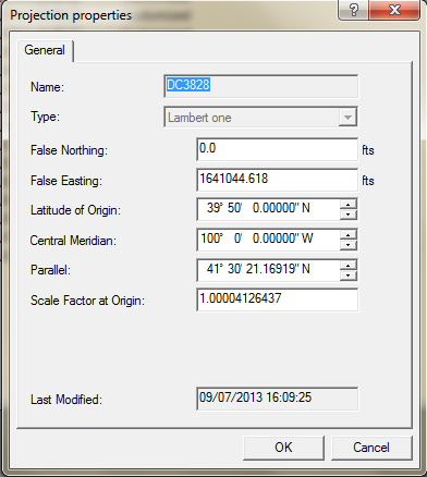
This is what I ended up with.
Got it
Will be interested to hear how things work.
I am a bit concerned about how the parameters you show seem to indicate the scale factor will be 1.00004126437 at 39° 50' N origin latitude (down in Kansas) instead of at the Bo latitude slightly north of 41° 30' N (about the north-south center of Nebraska).
BTW, after my previous post that included the parameters I noticed the "borrowed" Excel formula I used to convert from DD.d to DMS.s was truncating when it should have been rounding. A better value for Bo is 41° 30' 21.16920" N. Not much difference, but figured I should mention it.
Finally, if your LGO or other Leica software includes projections from around the world, it may be worthwhile to look at the projections for France. Their official projections are one-parallel Lambert and examining the entered parameters may help determine what should go where.
GB
Got it
Hit a few different control points and everything checks out good.
Thanks for all the help!


