> I'll be quite surprised if the light passes through the circle twice. I think the diagram isn't clear enough. I'm guessing it's a packaging thing, and two tiny mirrors are a way to have all the rest of the componentry above the circle.
The illustrations of the TS30 don't show the light path passing through the circle more than once, but all of those for the TPS1100 I've found do. I agree that it doesn't particularly make sense to run the light through the circle twice.
The TS30 literature does reference what it calls "minor ?-periodic errors which are determined by the system" and cites the additional pairs of angle encoders as the cure for that, which doesn't particularly make any sense to me.
Pictures for you.
Hello Kent,
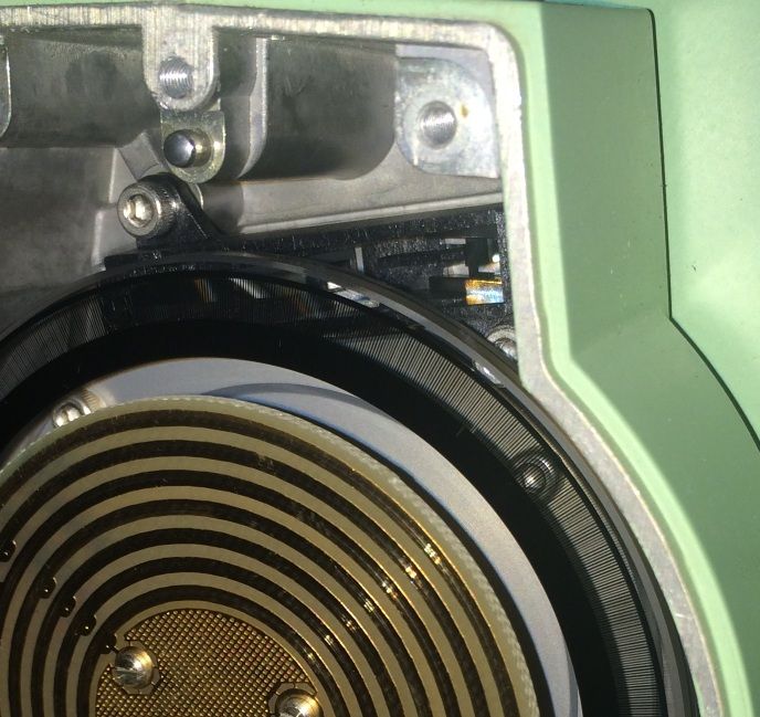
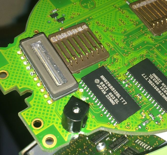
Here is a picture of the system in a TCA1105. I checked it. Light gets to first mirror clear of the circle, then off the second mirror, through the glass to the CCD array, all pictured. Only goes through once. Enjoy.


Pictures for you.
> Here is a picture of the system in a TCA1105. I checked it. Light gets to first mirror clear of the circle, then off the second mirror, through the glass to the CCD array, all pictured. Only goes through once. Enjoy.
> 
I take it the thing below the CCD strip is the light source and the circle doesn't extend beyond the curved edge of the board that both CCD and light are mounted on? It's hard to tell from the photo of the board where exactly the light paths is, but if you've examined them assembled, I'll take your word for it that the light path only passes through the circle once.
Pictures for you.
The diode is (in the photo) below the CCD array in the second picture. It is a red diode (to minimise scattering?) according to another piece I found.
In the first photo the black rectangular arrangement partly behind the circle is the mirror arrangement. When assembled and upright the diode is a bit higher than the CCD array and offset from the middle of the circle, which has the effect of clearing the light beam from the circle. It enters the first mirror which you can see is also upwards and offset from the circle. Then onward to be reflected back through the circle and read by the CCD. While not pictured, the second, diametric CCD and diode were there too.
8 little hex bolts and 15 minutes. Was worth it to have a look after reading about it.
Pictures for you.
> 8 little hex bolts and 15 minutes. Was worth it to have a look after reading about it.
I commend you for your bravado. I've been known to take things apart to see how they work, but just looking at that glass makes me nervous! Put that thing back together, will you please.+o(
Pictures for you.
Hello rfc,
The 15 minutes included reassembly actually; I didn't have it open for long.
Probably of interest, as the diode and CCD are on the board, pulling it out and reassembly would have moved the CCD with respect to the circle and this instrument probably would have required a vertical collimation adjustment. The board was a tight fit, and had pins to position and hold it in pretty snug, but we are only talking minute movements of the CCD to change the readouts.
Pictures for you.
> Probably of interest, as the diode and CCD are on the board, pulling it out and reassembly would have moved the CCD with respect to the circle and this instrument probably would have required a vertical collimation adjustment. The board was a tight fit, and had pins to position and hold it in pretty snug, but we are only talking minute movements of the CCD to change the readouts.
Which raises the question of what, if any, effects there are from the two circle readers not being exactly diametrically opposite. The other interesting thing to me is that seeing that photo brings home the fact of how comparatively large the CCD assembly is in relation to the coded graduation track. The gaps read by the CCD pixels are hardly nice and parallel at the extremities of the CCD assembly.
It would be interesting to draw out the pixels overlaid on the coded graduations to scale to see whether there are some effects due to the non-parallelism of graduations and pixels moving toward the edges of the CCD.
> 
What does a moving mean look like? That is, could you further improve the accuracy of the reading with a lookup table giving additive constant corrections that change at __ intervals?
Pictures for you.
> Which raises the question of what, if any, effects there are from the two circle readers not being exactly diametrically opposite.
Probably not much i'd imagine. We're talking about an eccentricity which should be easily recognised by being somewhere roughly opposite on the circle if my thinking is reliable.
>The other interesting thing to me is that seeing that photo brings home the fact of how comparatively large the CCD assembly is in relation to the coded graduation track. The gaps read by the CCD pixels are hardly nice and parallel at the extremities of the CCD assembly.
Actually you could make the gap parallel by compressing the mask instead. But, yes, I was surprised at the size of the CCD. Perhaps the dimensions have changed since the paper you posted?
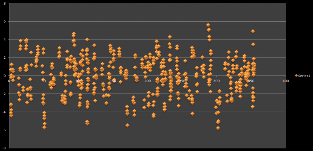
I might have a look tonight after I add the second sine term. I may have run in to the end of what precision is achievable, and what effects are detectable in my amateur, small-scale test range.
Pictures for you.
> >The other interesting thing to me is that seeing that photo brings home the fact of how comparatively large the CCD assembly is in relation to the coded graduation track. The gaps read by the CCD pixels are hardly nice and parallel at the extremities of the CCD assembly.
>
> Actually you could make the gap parallel by compressing the mask instead. But, yes, I was surprised at the size of the CCD. Perhaps the dimensions have changed since the paper you posted?
It doesn't seem likely, though, that Leica would have changed a part as critical as the CCD in the middle of production since presumably that would have required an entirely different board to mount the thing to and I believe the performance of the circle reader (CCD) quoted in the Croation article is comparable to that quoted for even the TS30.
Pictures for you.
This page suggests a size of the CCD of 3.2mm. That's why I was expecting something smaller.
Clearly it's not 3.2mm in the photo, and the detector spans more than 10 gaps. Perhaps the paper you referenced describes an earlier incarnation? Well, I'm not going to figure it out. I just trust that it works, only as well as Leica want it to work for my 5" model 😉


