Hi guys,
I'm hoping someone might be kind enough to help me with this. Let's say we do a Topo survey of house with property of about 2000sqm.
There is maybe a main house,detached double garage,swimming pool,large garden, trees, and then inside of house needs to be measured using tape measured as a sectional title would be.
Prep time : 1 hour (find trig beacons,TSM or old control closeby)
Survey time : 45min - 1h30 (establish GPS control)
3 - 4 hours (conventional total station survey)
1hour - 1h30 (measure inside with tape)
Office : 1-2 hours ( download data, reduce network and get ready for drawing of plan)
My problem comes in here. Currently this 6 hour survey requires another 6 hours to draw. I feel as if this process is slow. Are these times common,slow or fast?
We use Trimble R4/R8 and S3,5,6 (all running with TSC2 or 3 with access) and taping done traditinally with pencil,paper,clipboard and disto.
Reductions are done in EasySurv (local software) , imported into modelmaker for contour creation, then to ACAD for srawing with no add-ons or after reduction is sent to microstation with terramodel add-on. Final prodcuts are DWG and PDF.
Is there anything to increase the speed? And if so I assume some field procedure would need to adapt to the office software.
Modelmaker does have a "draw by DTM" feature that connects lines base on incrementing tag eith similar code but it is fairly useless.
Any help would be great. Or am I just being a over needy youngster that doesnt know what I'm talking about.
Have been using this systen for nearly 7 years with little change and that doesnt seem right to me.
Thanks in advance for any help
Dirkie
My first hands on with ACAD was v4 and any drawing was time consuming.
With software like Carlson (one among many) that has all the addons and features that will create or import anything and everything the drawing needs.
It will import the information of your field survey directly from your data collectors into a template for you to create the contours and has COGO routines and will analyze the survey and all the drawing tools and your time factor will become considerably less.
Of course there will be a learning curve, mine was printing the manual and going thru it non stop until I put out my first rather simple boundary survey drawing. I did have to squeeze info from a few others that used the program and hunt and peck for the commands.
RSAsurv, post: 382636, member: 10950 wrote:
sent to microstation with terramodel add-on. Final prodcuts are DWG and PDF.Is there anything to increase the speed? And if so I assume some field procedure would need to adapt to the office software.
Modelmaker does have a "draw by DTM" feature that connects lines
Dirkie
Why are you using so many different software applications? Just keep it simple.
Suggest you learn to use proper feature coding in your data collection, then your CAD system will draw the features, connect the line work and create the DTM at the time of download. Only "hand drafting" in CAD would be the labeling and annotations. For us 8 hours of field work equates to 1-2 hours of drafting. We are actually drafting in the data collector. The prism pole is your pencil.
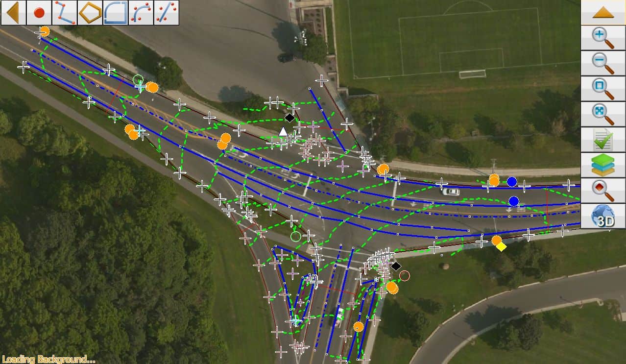
Here is a screen capture of what we see in the field controller. All lines, and the DTM are generated in the field controller. This is from 350 survey locations in 2 hours of field work.
@harris. Thanks I will try and get a copy of Carlson. Heard much about it abut havent tried it out yet.
[USER=1128]@Lee[/USER]. The reason varies. Acad because thats what I learnt to draw in and is simple to use, and presents better at the end. Microstation is mainly used with terra when I have to do classification of point clouds (MLS,ALS, TLS,UAV). Dont like it mich beyond that. Modelmaker is also used as it is a cheaper local version of something like Civil 3D (which I also use). Modelmaker is very simple for volumes,quick contours, basic drafting etc. Our fearure coding is done in such a way as to accomodate modelmaker. Your DC interface looks great. What are you using? Im stuck with either a TSC2 or TSC3. Older but works
I use so many different softwares because currently a single one doesnt do everything I want it to do (Im pretty sure civil 3d is my best bet but I just dont get a proper chance to fiddle enough). Between laser tracking, boundary surveys,topo surveyes, UAV, MLS and terrestrial scanning I have to register point clouds, model in Revit, draw deformation stuff on machines etc etc so never do just 1 thing. And then you know you can do what you need in modelmaker quicker rather than figuring out civil 3d for that problem and you just never learn.
Thanks
Sent from my SM-N920C using Tapatalk
That photo shows Topcon Magnet Field on a Panasonic FZ-M1 controller.
Certainly there is not just one software to do all the task you described. But for the single task you posted about (topo mapping) there are less steps with the right application.
I work with many apps for multiple tasks:
- Microstation and InRoads is my primary CAD application since 1993 for Highway design, boundary, topo, point clouds mapping, 3D modeling of highways, cell towers, and renderings.
- Carlson TakeOff for 3D site design, 3D models, and TakeOffs.
- Pix4Dmapper for UAV mapping, DTM and generate Point Clouds
- Topcon Magnet Field and Magnet Office Tools for data collection and reduction of Robotic TS, GNSS and Digital level.
That is certain more than I care to pay the maintenance fees on. But in the end, I find it much more efficient and enjoyable when using the correct tool for the job.
Thanks. That exactly what I was thinking about softwares. I really want to cut back on all the different suites. Will go do some research and see what I can find to use on the TSC2/3 that can improve the data collection variable
Sent from my SM-N920C using Tapatalk
Unless you understand and use field to finish, the old stand by, 1 hour in field = 1 hour in office applies to hand or CAD drawing.
Paul in PA
leegreen, post: 382692, member: 2332 wrote: Why are you using so many different software applications? Just keep it simple.
Suggest you learn to use proper feature coding in your data collection, then your CAD system will draw the features, connect the line work and create the DTM at the time of download. Only "hand drafting" in CAD would be the labeling and annotations. For us 8 hours of field work equates to 1-2 hours of drafting. We are actually drafting in the data collector. The prism pole is your pencil.Here is a screen capture of what we see in the field controller. All lines, and the DTM are generated in the field controller. This is from 350 survey locations in 2 hours of field work.
Don't want to take the thread too far off its intended path, but...
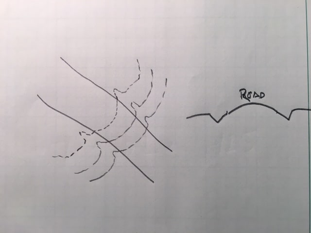
Your drawing seems to show changes in the topo across a road and into a ditch between only two points, one at either side of the road.
If you had a road with camber, and ditches on both sides, are you saying the software draws the topo the correct way, without having to record a gazillion points down into the ditch and over the road? Or can you manipulate the contours in the field, based on simply looking at the situation? 
rfc, post: 382766, member: 8882 wrote: Don't want to take the thread too far off its intended path, but...
Your drawing seems to show changes in the topo across a road and into a ditch between only two points, one at either side of the road.
If you had a road with camber, and ditches on both sides, are you saying the software draws the topo the correct way, without having to record a gazillion points down into the ditch and over the road? Or can you manipulate the contours in the field, based on simply looking at the situation?
RFC,
Look closer at the image and you will see nodes every å±50' along the break lines in a cross section fashion. I use a cross section method locating each break then ground shots in flat areas. So to answer your question, YES this software does generate the tin model and contours from the break lines and spots elevation. Pretty basic and standard for today's surveyor.
Here is a sample of feature coding used:
111,1101453.34800,943062.74200,556.54700,EP1 ST
112,1101453.85800,943069.72200,556.65900,EP1 PC
113,1101452.96300,943062.76400,557.21000,TC1 ST
114,1101453.41300,943069.80000,557.32500,TC1 PC
115,1101447.74400,943084.70500,557.83900,TC1
116,1101447.95700,943085.15300,557.41800,EP1
117,1101430.29800,943090.57800,558.48200,EP1
118,1101430.36600,943090.15800,559.02200,TC1
119,1101421.60800,943086.71100,558.83300,EP1
120,1101421.93700,943086.34000,559.35900,TC1
121,1101418.49800,943082.88500,559.10100,TC1
122,1101415.98600,943078.68600,559.10400,TC1
123,1101414.42700,943073.38800,559.52600,TC1
124,1101413.95000,943073.60600,559.13500,EP1
125,1101414.81100,943064.66700,559.03100,EP1 PT
126,1101415.35800,943064.75400,559.51000,TC1 PT
127,1101427.40600,943033.51800,558.61300,TC1
128,1101427.03600,943033.28800,558.26800,EP1
129,1101438.66600,943005.19300,557.70700,EP1
130,1101439.13200,943005.38200,558.00300,TC1
131,1101451.59100,942976.80100,557.25100,TC1
132,1101451.18200,942976.71900,556.88000,EP1
133,1101467.70600,942939.59300,555.69600,CB
134,1101468.30900,942940.06600,555.68500,EP1
135,1101468.50800,942940.06200,556.19000,TC1
137,1101467.58800,942949.48000,556.83600,UTP
138,1101466.85900,942952.22700,556.73300,UTP
139,1101474.12700,942937.50000,556.15700,SMH
leegreen, post: 382793, member: 2332 wrote: RFC,
Look closer at the image and you will see nodes every å±50' along the break lines in a cross section fashion. I use a cross section method locating each break then ground shots in flat areas. So to answer your question, YES this software does generate the tin model and contours from the break lines and spots elevation. Pretty basic and standard for today's surveyor.
You're talking about the small white squares with the black dots? Those are "nodes"? Got a lot to learn about FTF'ing topo; don't want to hijack the thread though. This is Magnet Field though, yes? I can do some reading.
[USER=624]@Paul[/USER]. Well that currently the situation and thats what I want to improve so I will have to get my bum down and get going. I am thinking carlson f2f but will only get a chance tomorrow. Thanks
Sent from my SM-N920C using Tapatalk
Hi. Sorry I dont want to make another thread and was wondering if some of the more tech savvy guys can help. Is there any way to create a .jxl file for use in TBC for aerial processing using a non-trimble UAV. Currently using a DJI P2 Adv.
Thanks
Sent from my SM-N920C using Tapatalk
In my 40 year career, it is common that the field time will nearly equal the office time.
I dont care what new stuff you use,
Randy
I miss Eagle Point.


