Bill93, post: 366395, member: 87 wrote:
Stupid question #N+1 : I think a LDP has less arc-to-chord correction by having the standard parallel and meridian close to your project. Is that true?
Yeah...I guess...I've never really thought about it!
Considering the "postage stamp" nature of most LDPs relative to the "Beach Blanket" nature of SPC Zones (not to mention UTMs or Montana), the difference between the "arc" and the "chord" doesn't amount to much.
First, one has to get the "PLANE" in State Plane out of their head to start with.
The State "Plane" Coordinate System(s) are NOT "PLANES" in the geometric sense, but 3d developed surfaces that "can be laid out" FLAT (as on a PLANE surface).
In the case of a Transverse Mercator, the [North-South] "arc-chord" issue is essentially moot, in that the developed surface is [in effect] a cylinder. The Lambert developed surface is a cone. The East-West (Transverse Mercator) or North-South (Lambert) arc-chord variances are of course dealt with via the [grid] Scale Factor (k) progression. This gets a little weirder when dealing with Oblique Mercator (Hotine) projections.
Of course "tangent planes" are another issue.
I hope that made sense...
Loyal
Tom Adams, post: 366417, member: 7285 wrote: SQ N+2
So it sounds like you are coming up with a little more specific multipliers for your specific sight. Do you still keep you bearings the same as the SP Grid bearing base Parallel to the origin longitude? or do you rotate your bearings to appear closer to what they are @ your longitude? I see in Shawn's article example that he was tying to a previous job that had used an astronomic observation.
I'm not sure that I can answer that...cuz I'm not sure what you are asking
Although I DO generate LDPs (Single Parallel Lamberts) from time to time to deal with UDOT projects, as a general rule, one of the PRIMARY reasons for an LDP (other than getting the distances "UP HERE"), is to more closely agree with the Original (True NORTHish) surveys from which all of the land entitlements (Patents) originated.
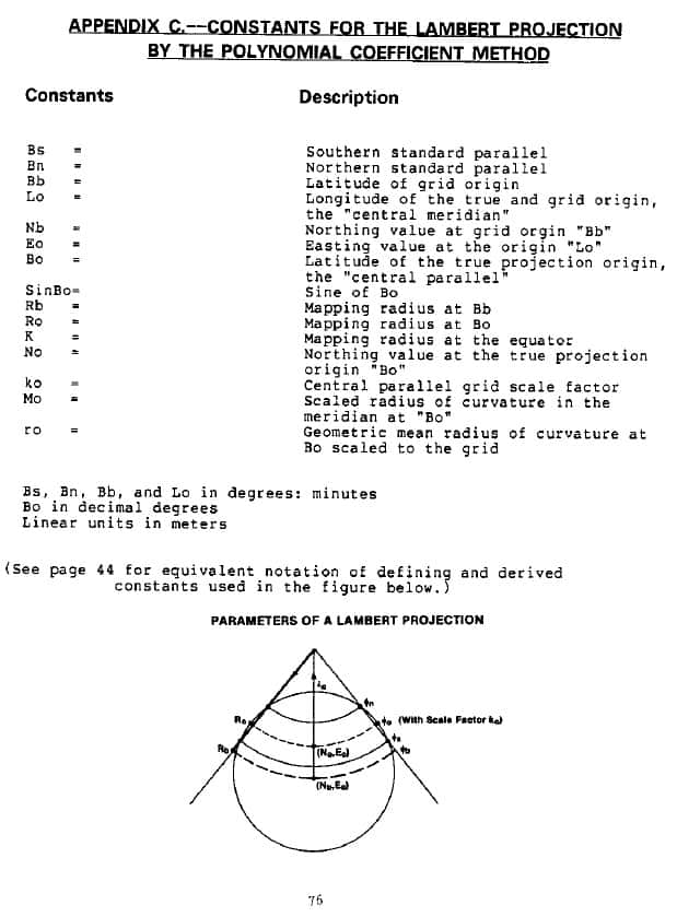
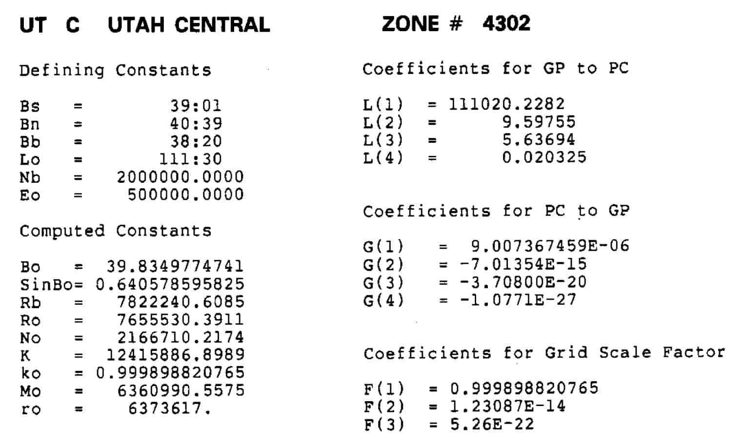
On note on dealing with Lambert DOTified SPCs... If you REALLY want to generate LDPish Northings & Eastings from Lat/Lon values, that AGREE with the DOTified SPC values, then you need to compute a Single Parallel Lambert using the "Bo" factor (see below);
Utah Central numbers below:
All the above stuff is in NGS 5
Loyal
For those that use TBC (can probably do something similar in other software packages).
You can edit the Points Listing to output the factors: Projection Scale Factor, Height Scale factor and Combined Scale Factor.
So once you have decided where your Origin (Central Meridian and Latitude of LDP) point is, create a point at the Lat, Long and Elevation you want for your grid to equal ground coordinates. Output the point listing for this point. Inverse the Elevation Scale Factor and use this for the Scale Factor for a Transverse Mercator Projection (a small one maybe 10 miles wide).
Use the Change Projection to create a projection using your Lat, Long and False Northing & Easting and use the inversed elevation factor as the scale factor in the projection. To check then run the points listing and the Combined Scale Factor should be 1.00000000 or very close.
Now you can run reports and inverses and compare the ground distances to the grid distances and the ellipsoid distances to see how it all works out for a project.
Tom Adams, post: 366454, member: 7285 wrote: Thanks MightyMoe, Do you publish additional lats and longs, or SPCoordinates, and or, project specific coordinates? Or simply the bearings and distances. I trust it's still on a State Plane Bearing base? You don't adjust bearings of lines based on convergence angles I am guessing. What does you BOB statement look like?
Also, do I automatically know what your "combined scale factor" is by definition? A lot of guys around here use a factor that would convert a SP distance to a ground as-measured distance which is always greater than 1 (since the lowest elevation in this State is above 3,300 feet. However, I see the definition of combined factor as being the factor that would take you from a ground distance to SP, which would typically be 0.999XXX.
I have seen a few articles or teaching programs, that use the term to go from SP to ground as being the "Ground Scale Factor" to differentiate it from "Combined scale factor". I know this if off-topic of LDP a bit, but, being kind of picky, just wondering. I almost think it would be better to publish the "Grid Scale Factor" and the "Height Scale Factor"
Most of the programs I use and my vendors use treat the factor as a multiplication, the combined factor was developed to get a ground distance to grid, hence you took the grid scale factor times the inverse of the elevation factor; at 3300 feet probably got a number like .9998 or .9997, this of course was multiplied by the ground distance and you get 9998 ft on the grid from 10,000 ft on the surface.
But what is happening here with the program is that it is creating a transverse mecator projection using the same data that creates state plane NAD83 projections. I have just shifted the origin point and gave it my own coordinates. This program now will accept a scale factor to get me off the ellipsoid to ground, I have to give it that as a multiplier. Hence the 1.00019:
Other programs may treat this differently but the two main ones I use treat it this way. Usually I see the DAF or Combined Scale Factor expressed this way, it's not only me, but if I see it as the inverse I know what they mean.
And no, I'm not on state plane bearings. If I want state plane bearings there would be no reason for me to create an LDP, I really don't care about the distance conversion, that is a trivial exercise in state plane, it's the bearings that I want to adjust, in the case of this project I have work in a number of townships and I wanted bearings to be close to true north,,,,,,much simpler to look for corners and maybe even prorate (gag) one in if I need to.......I only needed to set three and those were along a township line so the bearings weren't really important to do that.
If for some reason I want to publish coordinates there needs to be more metadata, (the false northing, false easting, the coordinates used for the CORS stations) but in this case it's a plat with some elevations, lats, longs, bearings and distances.
Frankly, I'm getting away from doing LDP's because so many users want state plane anyway, it's not difficult to convert these coordinates to state plane, I usually just export the lat, long numbers into a file set up as state plane, but it's way easier to work in state plane and not keep going through the exercise. However, in some areas, say near the east line of Montana working in the PLSS when the convergence to state plane is 4 degrees, the distances are terribly off, then a LDP looks really good
MightyMoe, post: 366504, member: 700 wrote: Most of the programs I use and my vendors use treat the factor as a multiplication, the combined factor was developed to get a ground distance to grid, hence you took the grid scale factor times the inverse of the elevation factor; at 3300 feet probably got a number like .9998 or .9997, this of course was multiplied by the ground distance and you get 9998 ft on the grid from 10,000 ft on the surface.
But what is happening here with the program is that it is creating a transverse mecator projection using the same data that creates state plane NAD83 projections. I have just shifted the origin point and gave it my own coordinates. This program now will accept a scale factor to get me off the ellipsoid to ground, I have to give it that as a multiplier. Hence the 1.00019:
Other programs may treat this differently but the two main ones I use treat it this way. Usually I see the DAF or Combined Scale Factor expressed this way, it's not only me, but if I see it as the inverse I know what they mean.
And no, I'm not on state plane bearings. If I want state plane bearings there would be no reason for me to create an LDP, I really don't care about the distance conversion, that is a trivial exercise in state plane, it's the bearings that I want to adjust, in the case of this project I have work in a number of townships and I wanted bearings to be close to true north,,,,,,much simpler to look for corners and maybe even prorate (gag) one in if I need to.......I only needed to set three and those were along a township line so the bearings weren't really important to do that.
If for some reason I want to publish coordinates there needs to be more metadata, (the false northing, false easting, the coordinates used for the CORS stations) but in this case it's a plat with some elevations, lats, longs, bearings and distances.
Frankly, I'm getting away from doing LDP's because so many users want state plane anyway, it's not difficult to convert these coordinates to state plane, I usually just export the lat, long numbers into a file set up as state plane, but it's way easier to work in state plane and not keep going through the exercise. However, in some areas, say near the east line of Montana working in the PLSS when the convergence to state plane is 4 degrees, the distances are terribly off, then a LDP looks really good
I input your projection and an Origin point at Elevation 3300 feet. I listed the point and it has an Elevation Scale Factor of 0.9998449767. The inverse is 1.000155047. I changed the projection and entered the Scale Factor as 1.000155047. Then Listed the points as Global and Grid. the Combined Scale Factor is now 0.9999999997 or 1.000000000.
The grid and ground distances at 3300 feet elevation will now essentially be equal.
Here is the results from the point listings
ID Origin
Latitude N43å¡30'00.00000"
Grid 20000.00 North
Longitude W104å¡25'00.00000"
Grid 20000.00 East
Height 3249.617
Elevation 3300.000
(US survey foot)
........................Before Adj. Scale Factor.....After Adj. Scale Factor
Scale Factor ________________ 1.0000000000 ______________ 1.0001550470
Height Scale Factor _________ 0.9998449767 ______________ 0.9998449767
Combined Scale Factor________ 0.9998449767 ______________ 0.9999999997
LRDay, post: 366539, member: 571 wrote: I input your projection and an Origin point at Elevation 3300 feet. I listed the point and it has an Elevation Scale Factor of 0.9998449767. The inverse is 1.000155047. I changed the projection and entered the Scale Factor as 1.000155047. Then Listed the points as Global and Grid. the Combined Scale Factor is now 0.9999999997 or 1.000000000.
The grid and ground distances at 3300 feet elevation will now essentially be equal.Here is the results from the point listings
ID Origin
Latitude N43å¡30'00.00000"
Grid 20000.00 North
Longitude W104å¡25'00.00000"
Grid 20000.00 EastHeight 3249.617
Elevation 3300.000
(US survey foot)........................Before Adj. Scale Factor.....After Adj. Scale Factor
Scale Factor ________________ 1.0000000000 ______________ 1.0001550470
Height Scale Factor _________ 0.9998449767 ______________ 0.9998449767
Combined Scale Factor________ 0.9998449767 ______________ 0.9999999997
That looks right Leon, it's quite a bit lower than my project, but if I were at 3300 ft 1.000155 might work out.
I usually try to pick a scale factor that is workable throughout the site, basically I design the LDP in the office depending on the location and terrian.
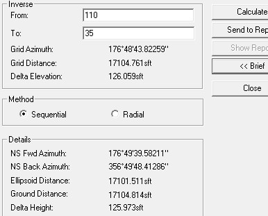
For the above example an inverse on the north part (higher elevations) of the job looks like this:
as you can see I'm about .05' short in 17000' with my grid distance.
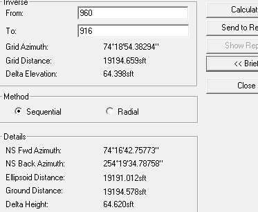
and an inverse in the south part of the job (lower elevations) looks like this:
There my distance is about .08' long in 19000'.
the idea is to get as close as you can with your site scale factor which is why I chose 1.00019
When you design a LDP using the standard parameters you are putting your coordinates on the ellipsoid just like state plane does so you still need to get up to surface somehow, in other words modify your LDP if you will.
This area has 400' or so of elevation change, pretty flat in these parts.
another interesting thing on the above inverses are the changes in elevation compared to the changes in height.
MightyMoe, post: 366577, member: 700 wrote: That looks right Leon, it's quite a bit lower than my project, but if I were at 3300 ft 1.000155 might work out.
I usually try to pick a scale factor that is workable throughout the site, basically I design the LDP in the office depending on the location and terrian.
For the above example an inverse on the north part (higher elevations) of the job looks like this:
as you can see I'm about .05' short in 17000' with my grid distance.
and an inverse in the south part of the job (lower elevations) looks like this:
There my distance is about .08' long in 19000'.
the idea is to get as close as you can with your site scale factor which is why I chose 1.00019
When you design a LDP using the standard parameters you are putting your coordinates on the ellipsoid just like state plane does so you still need to get up to surface somehow, in other words modify your LDP if you will.This area has 400' or so of elevation change, pretty flat in these parts.
another interesting thing on the above inverses are the changes in elevation compared to the changes in height.
Yeah, I'd round off the scale factor also and most of my projects have quite a bit of elevation change. Once a surveyor understands the basics here its really quite simple.
The way I convinced myself in the beginning was by inversing out a lot of distances in a real project and comparing ground and grid distances after I'd modified the scale factor. Once you get a handle on what is going on then you can get comfortable using this stuff.
I've also used the Oblique Mercator projection when I wanted to rotate the bearings to match some previous survey data.
LRDay, post: 366593, member: 571 wrote: Yeah, I'd round off the scale factor also and most of my projects have quite a bit of elevation change. Once a surveyor understands the basics here its really quite simple.
The way I convinced myself in the beginning was by inversing out a lot of distances in a real project and comparing ground and grid distances after I'd modified the scale factor. Once you get a handle on what is going on then you can get comfortable using this stuff.
I've also used the Oblique Mercator projection when I wanted to rotate the bearings to match some previous survey data.
I've used the Transverse Mercator for that also, but you have to be creative to get it to work, the problem I have using Lambert or the Oblique Mercator is some programs don't offer those as options beyond the established systems. Most seem to like the Transverse Mecator for whatever reason.
I do have a client who goes to the field, sets up on the highest spot starts his base and lets the DC make a modification to state plane at that point.
Of course it's the wrong scale factor, correct at the one high point but weak throughout the rest of the job. And it's always out to 9 or 10 places, which for this purpose is like a dog chasing it's tail.
Thanks for all the input. I got me some "studyin'" to do. But with all the advice, and reference links, I think I have enough material.
Bill93 said: Ô
Stupid question #N+1 : I think a LDP has less arc-to-chord correction by having the standard parallel and meridian close to your project. Is that true?
Loyal, post: 366473, member: 228 wrote: Considering the "postage stamp" nature of most LDPs relative to the "Beach Blanket" nature of SPC Zones (not to mention UTMs or Montana), the difference between the "arc" and the "chord" doesn't amount to much.
Further reading and calculation shows me that, for a given sighted line, the arc-to-chord correction depends on the distance north/south of a Lambert Phi-zero parallel or east/west of a Transverse Mercator central meridian.
So the smaller arc-to-chord correction is in whichever projection your example happens to fall closer to the standard line of the projection. In most areas it will be lower in an LDP, but in some small areas it could be lower in SPC because your sighted line lies near the SPC standard line.
Bill93, post: 367440, member: 87 wrote: Bill93 said: Ô
Stupid question #N+1 : I think a LDP has less arc-to-chord correction by having the standard parallel and meridian close to your project. Is that true?Further reading and calculation shows me that, for a given sighted line, the arc-to-chord correction depends on the distance north/south of a Lambert Phi-zero parallel or east/west of a Transverse Mercator central meridian.
So the smaller arc-to-chord correction is in whichever projection your example happens to fall closer to the standard line of the projection. In most areas it will be lower in an LDP, but in some small areas it could be lower in SPC because your sighted line lies near the SPC standard line.
Yup...that would be the case in the scenario that you describe. The vast majority of the LDPs that I have used over the years, are such that even the EXTREME limits of the LDP, don't even get in the same Zip Code as any of the SPC/UTM "central-meridian/central-parallel." There are a few exceptions, and in SOME cases, I have generated (designed) the LDP to return SPC bearings on purpose. Which isn't as easy as it sounds (in some cases)...
Loyal
Bill93, post: 367440, member: 87 wrote: Bill93 said: Ô
Further reading and calculation shows me that, for a given sighted line, the arc-to-chord correction depends on the distance north/south of a Lambert Phi-zero parallel or east/west of a Transverse Mercator central meridian.
I understand your statement but find it a little confusing. I would have written it, "...the arc-to-chord correction depends on the distance north/south of a Lambert explicit of implicit standard parallel."
That is, if you're using a Lambert conformal conic implementation that is defined by a latitude + scale factor (<1.0), that will effectively create two implicit standard parallels. Otherwise, you would have define it with two explicit standard parallels. The phi-zero parallel in the first case has the scale factor's distortion, while in the second case just identifies where the origin of Y/Northing values start.
Melita
mkennedy, post: 367447, member: 7183 wrote: I understand your statement but find it a little confusing. I would have written it, "...the arc-to-chord correction depends on the distance north/south of a Lambert explicit of implicit standard parallel."
That is, if you're using a Lambert conformal conic implementation that is defined by a latitude + scale factor (<1.0), that will effectively create two implicit standard parallels. Otherwise, you would have define it with two explicit standard parallels. The phi-zero parallel in the first case has the scale factor's distortion, while in the second case just identifies where the origin of Y/Northing values start.
Melita
Melita, excuse my ignorance, but can you expound on what "implicit and explicit" standard parallels are? Maybe I should already know this.
Tom
Tom Adams, post: 367455, member: 7285 wrote: Melita, excuse my ignorance, but can you expound on what "implicit and explicit" standard parallels are? Maybe I should already know this.
Tom
Let's say you define a conic projection with a single latitude--that's a tangent case, and that latitude is a "standard latitude" with SF = 1.0. If you then scale all coordinates by, say, 0.9999, you convert the projection into a secant case--the cone now cuts through the ellipsoid surface and the original latitude is now above the cone. There are now two new standard parallels, but we don't explicitly know their values without doing some calculations. Or, like in a state plane zone, you explicitly define the conic projection with two standard parallels.
CUNY's geography department has some good pictures but I was only able to view the cached versions through Google. I don't particularly like these, but:
Thank you Melita,
I read what you wrote, but I think I need to reread it and reread the posts that led up to it. I think I'm starting to gain some knowledge, but have to develop the wisdom (implicit in another thread) 😉


