Many, many years ago on a message board for surveyors far, far away, I posted an example of how to easily evaluate the centering error of a total station that I think remains a pretty good way to get a realistic value of the standard error of centering to use in a least squares adjustment, which is important. That is, the fact that the instrument used to measure an angle isn't exactly, absolutely, perfectly centered over the ground mark from which an angle was supposedly measured does need to be taken into account in figuring what the actual uncertainties in that measurement really are (unless one is traversing entirely by forced centering with essentially zero centering errors).
It isn't any difficult problem for a Star*Net user to work. The test procedure I described consists of:
a) setting some ground mark that is typical of the sort of mark that the instrument will be set up over in ordinary work (Doesn't matter whether it is a punchmark on a spike, a tack in a hub, a 60d nail with no mark on the head, or a 6 in. x 6 in. stone planted in the ground. The idea that the mark should be typical of what is actually used.),
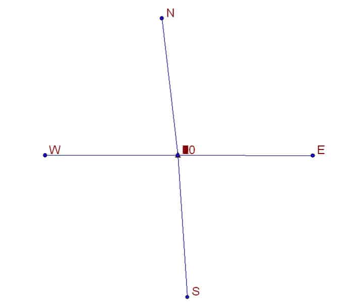
b) setting some ground marks about 7.00 ft. distant N, S, E, and W of the central mark that have a definite feature like a punchmark or something else that a total station can be pointed on with very small uncertatainty, i.e. a good clean mark to align the telescope reticle with,
c) measuring the distances from the central mark to the N,E,S, and W marks, either by taping or by EDM. An uncertainty of +/-0.02 ft. is fine and 0.01 ft. or less is better.
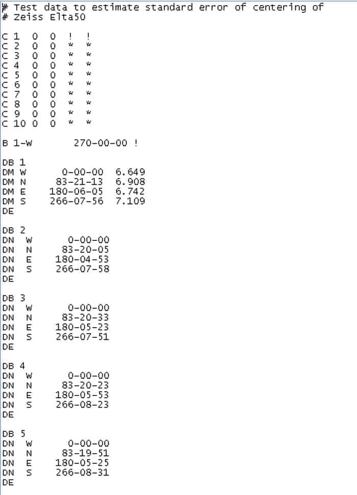
The surveyor simply sets up the total station over the central mark using whatever procedure is customary and measures directions to the N,E,S, and W marks. The initial setup is arbitrarily assigned a coordinate of N=0.00 E=0.00 and the direction from it to, say, the N mark is fixed as 0å¡00'00". From those conditions, the least squares adjustment should be able to compute the coordinates of the N,E,S, and W ground marks.
You may rightly deduce from the above that there is no requirement that the N-S and E-W axes be exactly perpendicular or that the instrument station lie exactly upon either. Merely roughly so in both cases is sufficient.
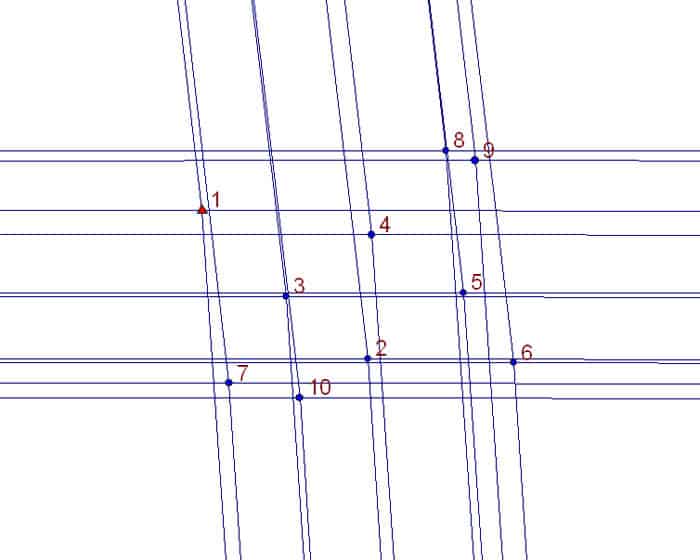
The test consists of setting up the total station ten times over the central mark from scratch, rotating the tribrach by about 40å¡ between setups so that the tribrach turns roughly the full circle in orientation for all ten setups, and measuring sets of directions to the four ground marks, N,E,S, and W.
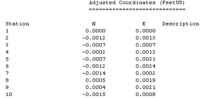
From those four directions observed at each setup, the coordinates of the setup can be calculated by resection. The geometry of the situation is such that the relative coordinates of the various setups are much more accurate than the relative coordinates of the N,E,S. and W ground marks. The scatter of the coordinates of the ten setups gives enough data to calculat e the standard errors of the N and E components of the setup coordinates, which, being on nominally the same point should in theory be identical, but will contain the small, random centering errors of the method used to set up the instrument over the ground mark.
Since the tribrach is rotated between setups, it is reasonable to assume that the mean of all is free of any bias, i.e. that it is nominally over the center of the ground mark subject only to the small random errors in each setup.
So, based upon the above, what are the standard errors of the N and E components of the ten different setups over the same point? If you said:
+/-0.0007 ft. or 0.21mm for the N components and
+/-0.0008 ft. or 0.24mm for the E components,
I would agree with you.
So, for that instrument tested above, a modest Zeiss Elta 50 with an optical plummet that rotated with the alidade, a standard error of instrument centering of less than 0.0001 ft. would be reasonable as a setting in Star*Net to use in adjusting angles measured with the instrument.
Hey Kent: I did this, it seems like a year and a half ago. There was so much wrong with my set up and my procedures though, I might just have to give it a whirl again.
I've been using .005' for my ever expanding control network, but I'll bet that with the number of setups under my belt since then, it's probably gotten better. Did you use "DN" lines in Star*net?
Thanks for the refresher.
Kent McMillan, post: 376798, member: 3 wrote:
The test consists of setting up the total station ten times over the central mark from scratch, rotating the tribrach by about 40å¡ between setups so that the tribrach turns roughly the full circle in orientation for all ten setups, and measuring sets of directions to the four ground marks, N,E,S, and W.
However, if you aren't using a round-head Zeiss tripod, but one with a triangular head, make that "rotating the tribrach by 120å¡ between setups and make some even multiple of three setups. Nine would work. The idea is just to have them evenly distributed in differing orientations.
Kent McMillan, post: 376798, member: 3 wrote: So, for that instrument tested above, a modest Zeiss Elta 50 with an optical plummet that rotated with the alidade, a standard error of instrument centering of less than 0.0001 ft. would be reasonable as a setting in Star*Net to use in adjusting angles measured with the instrument.
And that should of course be: "a standard error of instrument centering of less than 0.001 ft. would be reasonable".
BTW, for those who are interested, here is a link to an earlier thread on the same subject :
https://surveyorconnect.com/community/threads/testing-centering-errors-of-a-total-station.271086/
Those results put you right in there with the specs on these two products, where I work we often use the Leica carrier.
I like the look of the FPM product better but have not used it, I noticed it was the tool used by the Geodesist who comes in to check our alignment.
http://www.fpm.de/lang_en/index.php?c=1&s=plumb
Optical Plummet FG-OLN
Technical data
Centring accuracy
+ 0,25 mm on 1,5 m
Focusing distance
> 0,5 m
For centrig over ground marks, optional with center spigots to the DIN or a turtle clamp to the WILD, rotable axis system and horizontal window.
3-times magnification
cross levels: sensitivity 2Ûª/ 2 mm
http://www.leica-geosystems.us/en/Carriers_84827.htm
GZR3, Precision Carrier with Optical Plummet
With high accuracy optical plummet and longitudinal bubble for exact positioning over measurement points. Reflector centring accuracy 0.3mm, plummet accuracy 0.5mm at 1.5m.
Order No: 428 340
Kent, I would guess when it needs to be as accurate as achievable, simply meaning out the discrepancies in your plumb sight would bring you closer to a true center. Some plumb sight errors are concentric, others elliptical. Still the process should bring about the desired results. If the ground point isn't sufficiently mangled by a hammer you should be able to see 1mm discrepancy.
R.J. Schneider, post: 376835, member: 409 wrote: Kent, I would guess when it needs to be as accurate as achievable, simply meaning out the discrepancies in your plumb sight would bring you closer to a true center. Some plumb sight errors are concentric, others elliptical. Still the process should bring about the desired results. If the ground point isn't sufficiently mangled by a hammer you should be able to see 1mm discrepancy.
Actually, with a rotatable plummet, the standard procedure is to center over the ground mark, rotate to 180å¡ and shift the tribrach/instrument to a halfway position. Then rotate back to 0å¡ to verify that the "images" are symmetrical and then to 90å¡ and 270å¡ to check the same. You can center perfectly well with a plummet that is slightly out of adjustment as long as this procedure is used.
The same goes for centering a prism pole in a tripod. With an 8-minute vial on the pole, a standard error of centering of about +/-0.4mm should be possible without breaking a sweat as long as the bubble positions at 0å¡ and 180å¡ are symmetrical and ditto 90å¡ and 270å¡.


