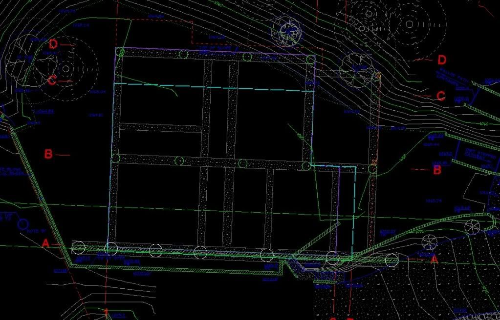
I have to vacate some boundary lines and to keep the colors and layers all uniform on the lines and bearing text and the leader arrows. But, because of the layer settings I need to change the line weight of the leader arrows. What is the default lineweight? Everything just says "default", but is it 0.05mm? 0.10mm?
Thanks in advance!!
Carl
I don't know what the answer is about default values, but I would go with 0.20mm - 0.25mm for good definition. Those are final print widths which are set up in the PDF plot menu that I use.
> I have to vacate some boundary lines and to keep the colors and layers all uniform on the lines and bearing text and the leader arrows. But, because of the layer settings I need to change the line weight of the leader arrows. What is the default lineweight? Everything just says "default", but is it 0.05mm? 0.10mm?
>
> Thanks in advance!!
>
> Carl
I should have mentioned that I'm using Carlson 2010 w.Icad 6.6. I figger that stuff is pretty standard, but who knows...
> I don't know what the answer is about default values, but I would go with 0.20mm - 0.25mm for good definition. Those are final print widths which are set up in the PDF plot menu that I use.
Thanks Paul.
I'll consider it. It's not hard to change, but I don't want to do a whole lot of testing.
> I don't know what the answer is about default values, but I would go with 0.20mm - 0.25mm for good definition. Those are final print widths which are set up in the PDF plot menu that I use.
It looks like you were right Paul. Thanks!!
I was actually able to find something in the "HELP" area... for once.
Setting a layer's lineweight
Each layer uses a default lineweight. Lineweights determine the thickness of entities both on the screen and when printed.
All new layers are assigned the DEFAULT lineweight, which is .25 millimeters or .01 inches. If you want a different lineweight assigned to a layer, you can easily change it using IntelliCAD Explorer. For example, you may want different lineweights on each layer of your drawing to show separate elements, such as walls, dimensions, structural steel, and electrical plans. Changing the lineweight assigned to a layer changes the lineweight of all entities drawn on that layer with the BYLAYER lineweight.
When you create new entities, it’s a good idea to assign the BYLAYER lineweight to any entities that you draw on that layer, unless you want to override the layer lineweight. IntelliCAD uses the BYLAYER lineweight as the default lineweight setting when you create entities (in the Drawing Settings dialog box).
Carl
http://freepdfhosting.com/98fec4309d.pdf
To really see the line weight differences of this PDF you have to zoom in. Hope this helps a little
Carl
>> http://freepdfhosting.com/98fec4309d.pdf
>
> To really see the line weight differences of this PDF you have to zoom in. Hope this helps a little
Thanks Paul,
Yeah, I get it, but I wanted them at the drawing standard rather then guessing.
It's all good now.
Thanks again!
Carl..Why by Layer ??
That's just a mess. Try by color, it will make your whole life so much easier.
I do my maps in certain colors when compiling them. Some are standard colors I use, some are colors that I just feel like using. It helps when sorting stuff out in a drawing.
When the drawing is ready to be plotted, I make a copy of the whole thing and start changing items from the creation color to the plotting color.
Ready to plot to a PDF

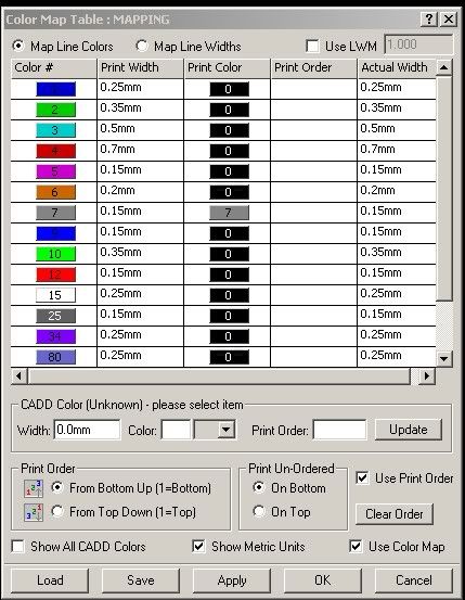
PDF plot menu - user defined

All my drawings are plotted out using colors 1, 2 , 3, 4 and 7.
Color 1 0.20-0.25 mm
Color 2 0.35 mm
Color 3 0.50 mm
Color 4 0.70 mm
Color 7 0.15 mm - 0.25 mm which is a screened color for fade backs.
Plotting ByLayer has always been a backward leap as far as I am concerned.
However, if you are stuck with that , then forge ahead, but if you can also do plot by color than try that out. Things will go a lot easier once you get your basic plot colors/line widths down in the plot menu.
PS Those other colors/line weights listed in the plot menu mean nothing at all, some residual changes I did for another drawing. Since only five colors actually exist in the plot drawing, 1, 2 , 3 , 4 and 7, thats all the PDF takes into account when making a file.
Carl..Why by Layer ??
uh.... ok.
I'm a very "school of hard knocks" kinda of user. I didn't even know I could do things like that. I only really use like 3 colors but I want stuff by layers in case I have turn them off later for some reason.
Carl..Why by Layer ??
>but I want stuff by layers in case I have turn them off later for some reason.
You can still do that. Filtering a dwg by entities is a great tool.
Carl..Why by Layer ??
"When the drawing is ready to be plotted, I make a copy of the whole thing and start changing items from the creation color to the plotting color."
I'm confused, are you saying you draw the whole plan then basically re-do the colors of the lines to get it ready to plot? that seems really odd, I hope I'm misunderstanding something there...
Carl...setup a CTB file.
C (color) or STB s being Style. It works well even with creating pdf.s. If you want more info call me....757-319-3273. I've never had a problem with Carlson (which is my current).
Carl...setup a CTB file.
Thanks Craig,
I'm fine for now. I just gotta get this thing finished.
Carl
Carl..Why by Layer ??
> I'm confused, are you saying you draw the whole plan then basically re-do the colors of the lines to get it ready to plot? that seems really odd, I hope I'm misunderstanding something there...
That's what I do. It's not hard at all. Why does it seem so odd to you? It's a 10 minute procedure, and that's only if I dink around doing it.
BTW..I copy the plan and filter that.
Also..
Basic items are always on their own input layer...all the time.
Shot numbers, shot tics, contours (in 2 different colors), shot elevations, etc etc..
Carl..Why by Layer ??
I think the reason that it's so odd is that it turns plotting from a 20-second task into a 10-minute task. And if you miss something, you get a bad plot. Seems like excessive and unnecessary effort.
We like using STB files, and divorcing colors from lineweight. That lets us have items in various colors that make the drawings much clearer to read on the screen, which is what it sounds like you're doing. Yet everything will also print to appropriate lineweights, and we don't have to change layer colors prior to plotting.
Carl..Why by Layer ??
> I think the reason that it's so odd is that it turns plotting from a 20-second task into a 10-minute task. And if you miss something, you get a bad plot. Seems like excessive and unnecessary effort.
Like..who is going to get on my ass for doing it the way I want to do it? I would rather spend an extra 10 minutes and find some corrections than hit a 20 second plot key and find them when reviewing the plot.
Thats the problem with surveyors, cept me of course, if it's not done thier way it has to be all FUBAR
Carl..Why by Layer ??
No reason to get on anybody's ass about anything. If somehow changing the colors for the plot is part of your routine and it helps you find errors, go for it. If you want to change everything to magenta and back again, fine with me. Personally, I like to create the lines and text on the layers with the colors that are going to plot with the line weights I want right off the bat. I think I would make more errors changing them to the right color at the end of the process. One thing I don't like about my system is that PL1, my basic interior boundary line layer is blue and it's hard to see on the screen, so I could see having a temporary layer for that and changing it before plotting, but I think I'd probably forget to do it half the time, I'm so used to doing it this way.
Carl..Why by Layer ??
I agree, I use the lineweight setting that AutoCAD has had for the past 10 years or so. Then I can make the layer whatever color I want because the first 10 colors or so plot black.
But this still seems to not be the common way it is done. Most are still plotting by color. I deal with that at work because the template drawing is set up to plot by color. When I am doing something that is only for me (a Corner Record or Record of Survey) then I do it my way but topos have to be done the company way because the Engineers have to use it.
Carl..Why by Layer ??
I dont use Autocad so what I do is probably a lot faster than if one would want to do it in Autocad. Here are some snapshots that show the simplicity of the commands.
CG (change) Command
Typing CG in on the command line brings up this sub command line.

To entity filter I then choose F from the above sub menu which brings the Filter command menu up
Filter Command

Though I have never used the More command, here is that sub command menu

So, if I want to filter all text that I want to plot at 0.25mm all I need to do is type in
CG F T
It's fast and easy to learn. Is Autocad as simple in it's structure?
> Everything just says "default", but is it 0.05mm? 0.10mm?
Those line widths are generally too thin, won't reproduce well.
Standard for leader lines for most DOTs and the military is 0.25mm, Leroy 000, 0.010 inches.


