
Activity Feed › Discussion Forums › Photogrammetry, LiDAR & UAS › UAS Contours
UAS Contours
Posted by gmpls on May 23, 2018 at 4:23 pm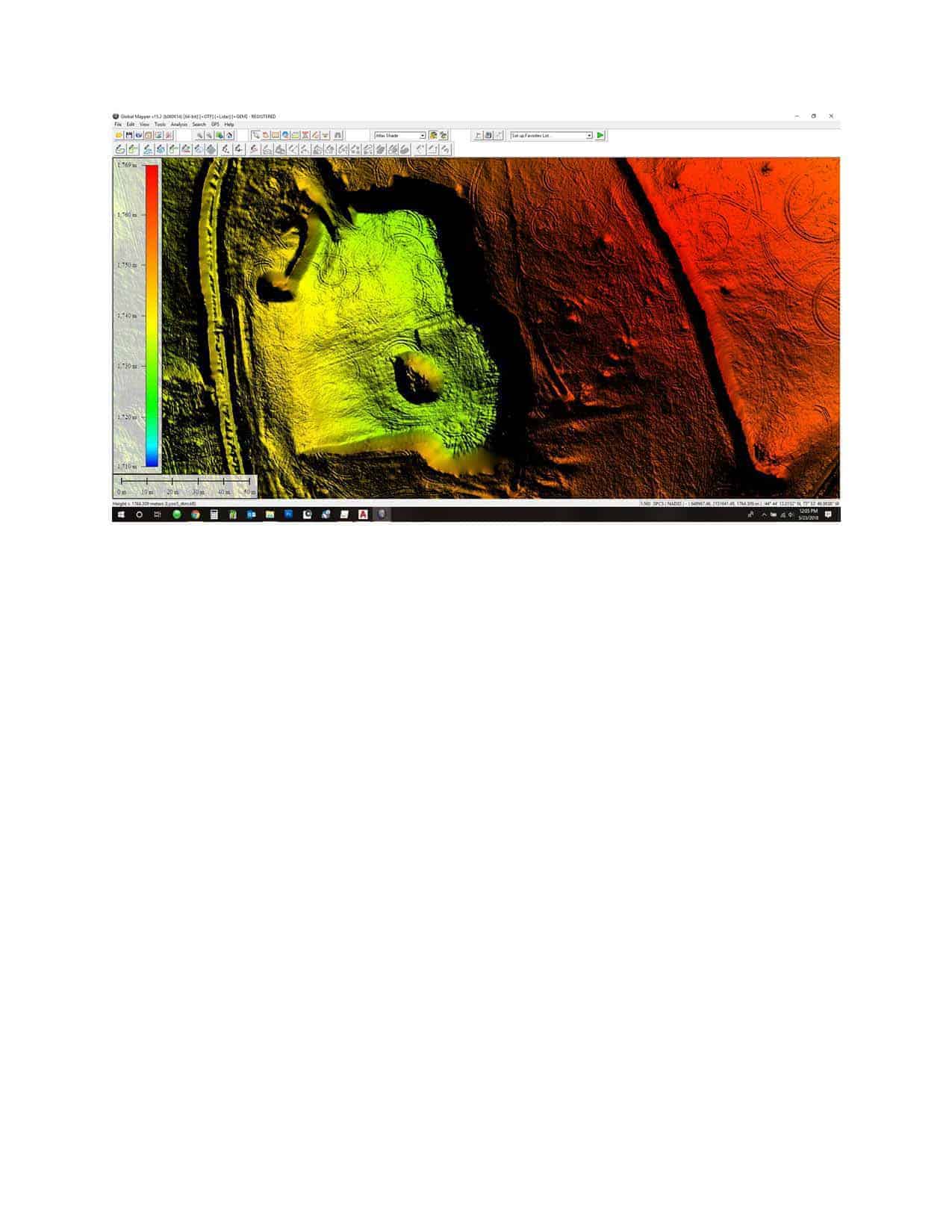
Last week I topo’d a mine tailings pit using a total station. This week I flew it with my Phantom 4 Pro. My results seem pretty good but it looks like I had issues with the dtm created contours (the area labeled “here” on the contour comparison). The blue contours were generated by Pix4D using the aerial photography and the gray by Acad based on the topo. Notice that the UAS contours are inaccurate in areas that look like shadows in the dtm. The other areas labeled “disregard” had a little material moved in between the topo and the flight that was used for the dtm and contours. The orthophoto shows that there is data there but it must get lost during dtm creation? Back to the drawing board I guess. Any comments or suggestions are appreciated.
Gregg
leegreen replied 5 years, 11 months ago 4 Members · 10 Replies- 10 Replies


What is your contour sampling resolution set to in Pix4D? You could try different sample sizes (i.e. 5, 1, or .30 m sampling size), that might better establish the base of your mound to contour. You don’t have to reprocess step three to get the different contour sampling resolution, under the ‘Process’ pulldown menu, after you have set your new parameters within the “Processing Options” (in the third step) and then ‘Generate Contour Lines (DTM)’. Pix4D will rapidly regenerate the contours for your review.

In the contour lines section of the additional outputs tab in processing options my resolution was set to 10cm. Is that what you were referring to?
Gregg
 Posted by: GMPLS
Notice that the UAS contours are inaccurate in areas that look like shadows in the dtm. The other areas labeled “disregard” had a little material moved in between the topo and the flight that was used for the dtm and contours. The orthophoto shows that there is data there but it must get lost during dtm creation? Back to the drawing board I guess. Any comments or suggestions are appreciated.
Gregg
My first impression is that there is insufficient image overlap near the pit high walls. In other words, two adjacent images do not both show the steep area near the top of the high wall. I don’t work with UAS, but have experience with satellite stereo pairs. Stereo imagery has issues in urban areas and where there are steep (near vertical) natural features. The French came out with a pair of satellites in 2012 that can produce tri-stereo imagery. The satellite is tasked with capturing three images for a given area. The first image is captured looking forward 15?ø, the second at nadir and the third image looking backward 15?ø.
Here is an 11-page PDF file Validation of Pleiades Tri-Stereo DSM in Urban Areas – MDPI that describes what happens and how tri-stereo imagery corrects the problem (see Figure 1. Stereo and tri-stereo views of the Pleiades-1 mission on page 2 of the PDF for a graphic). It shows the problem of seeing the street between two tall buildings using only stereo imagery.
First off, thanks for the pdf. I haven’t read it yet so I’m sorry if my next comments are covered in there.
Are you basing the overlap issue on the ortho photo? I ask because the ortho is from a different flight than the dtm and contours. I flew the site last week with a single grid and then this week with a double grid and a better drone. I didn’t post that ortho because its still being created.
Maybe I should do a pass at 70 or 80 degrees in addition to nadir in instances where the are tall vertical slopes?
Gregg
Gregg,
What I’m getting at is that one of the images of each stereo pair near the high wall may have a blind spot. For example, say the high wall is oriented N/S and your flight lines are E/W. If the principal point of the first image is in the bottom of the pit and the principal point of the second image is on the original ground surface, the second image will not see the top of the high wall because is is near vertical.
You would need to have the principal points of both images that comprise the stereo pairs to be in the pit. In other words, you need more image overlap near the high wall and the flight lines need to be closer to perpendicular than parallel to the high wall. A quick fix is to use the DEM created by your software, except near the upper portion of the high wall, and manually interpolate the area with errors.

It is the shadows. Pix4d creates adverse effects in shadow areas. Best to fly near noon, or when slightly overcast. This can be corrected by creating breaklines from the point cloud with software such as TopoDOT. You will see a thick area of the point cloud, then you can make an informed decision when creating the breakline using the lowest portion of the cloud points.
Lee,
Like I said, I am not familiar with the specifics of drones, the types of cameras used, nor software like Pix4d. Shadows can create more work, but are not a hindrance to processing satellite imagery. The reason is that nearly all of the newer platforms collect 11-bit data for each band on the satellite platform. The fact that the range of digital numbers is 0-2047 instead of single byte bands (0-255) allows me to stretch the area in shadow without losing information. I mask off the area in shadow, do a histogram-based stretch and mosaic it to the remainder of the image. It takes a wee bit of extra time, but the result is a seamless mosaic without shadows.
I’ve used DEM modules from two software packages; ENVI and Geomatica. Geomatica is more robust in my opinion (it can handle shadows without my input), but ENVI has better tools for evaluating the “fit” of the GCPs. A few years ago I created a 1-meter horizontal spaced DEM from Pleiades imagery with an areal extent of 1100 sq. km in west central Africa. The work was for a mining company.
What image format(s) is Pix4d able to process?
Pix4d processes JPG imagery, utilizing the embedded EXIF information.
So the point cloud is good but something gets lost in between there and the DTM? I haven’t looked at the point cloud yet.
Are there any ways to resolve the DTM shadows beyond flying at high noon or editing or adding break lines? Maybe flying those areas with a 70 degree camera angle? I’d love to fly a little later in the day but the wind usually picks up before noon around here.
This exercise has been a good learning experience for me. I’ll definitely be on the lookout for those shadowed areas in the DTM next time. Everything else looked pretty good and will probably look better when I fly in more calm conditions.
Thanks again Lee for your help.
Gregg
Using a 3d app like TopoDot you can cut a section at the subject area and see the point cloud. Then make an informed decision to create the break line. Pix4d us average the point cloud and can’t map an undercut with the the dtm.
I can set up a remote desktop sessions on your PC and show you.
Log in to reply.