
Activity Feed › Discussion Forums › GNSS & Geodesy › Removing Geoid for Machine control. (TRIMBLE)

Interesting, so is one of the main questions _whether or not it’s adequate to encode the geoid-adjusted heights into the NorthingEastingElevation point file?_
If @leegreen has a solution for loading geoids into the SCS900 (these guys seem to also suggest a method exists: https://prositeconsulting.ca/how-to-add-geoid-into-scs900-site/), is there still the remaining question about using one large calibration versus numerous small ones?
When I drop the grid csv it wants a project location, then when i drop the LLH it does the same. then I compute the project as you stated and my residuals are way off.
I’m still trying to wrap my head around how all the cute geodetic diagrams translate into real-world survey workflows, and my understanding comes in fits and spurts (so I’m probably off-the-mark with this comment), but seeing this prompt in TBC is my signal that I forgot to define the projected coordinate system that I intended to use as a starting-point for my project coordinates.
I’m doing this *before* I import anything, which makes me feel like I’m in more control of how the coordinates are being handled in TBC (and I usually type in an EPSG code, which is the fastest way I’ve found to define the particular coordinate system I prefer).
I think this might work for me because I work in State Plane at low elevations (~1000ft or less), I do not have any settings checked for computing ground distances, and I work on small-enough projects that the convergence angle associated with my OPUS processed base station is pretty representative of Grid North (and I’m not laying out bolt patterns or bridges).
Thinking about your situation, and assuming that you’re working in some UTM or State Plane projection, I am curious if it might still be helpful for you to establish the parent coordinate system first, import your files, then work through TBC’s calibration utility.
I’m not sure why this approach might be preferable.. is it because choosing your parent projection pre-loads the False Northings/Eastings, datums, geoid and HTDP? I’m also not sure when you’ll need to instruct TBC to use [the surveyors?] chosen location(s) for calculating Grid and Elevation Scale Factors.. but after your calibration is set, isn’t the only remaining decision about using grid versus ground?
Assuming the project has UTM or State Plane Coordinates, is it easy to import global LLH into TBC and correctly define the system they are associated with? Assuming it’s easy to do in TBC, would you ever use an EPSG in TBC to define the Global coordinate system? Would you use EPSG 4326 (the original definition for WGS84)? Or EPSG 9754 (the most recent update to WGS84, having been adjusted to coincide with ITRF2014)? (Which one is TBC using by default? Which one is our data collector using?)
If you used Local Coordinates, I’d probably choose EPSG 6318 for NAD83(2011), unless another realization of NAD83 was being used.

When the job is set-up select the proper projection such as State plane zone xxxx NAD 83 (Conus).
At that point enter in the LLH from whatever epoch of NAD83 you have under Global Coordinate and the Local Coordinate should be identical with the Global Coordinate. You can also enter in xyz for each point under Grid.
The program will calculate the proper xyz numbers if you enter in Global Coordinates or the proper LLH Global Coordinates if you enter in xyz grid numbers.
It’s up to the user to track what epoch is in use for the project.
Once a calibration is applied the projection is lost and the Local Coordinate will change slightly.
The easy way to check that the process is being correctly applied is to print out a local data sheet and compare the numbers.
Generally speaking, the only time that I will ever calibrate with control that is in a defined projection from a defined datum is when I am forced to set up the base over an unknown point…which is extremely rare. If the control is supposedly in a projected (or projected + ground-scaled) system, there should be no other reason to calibrate.
If a job is “in state plane” or “on modified state plane ground” and we have to calibrate to get things to line up, that means someone ****ed up along the way, either during the initial control/adjust phase, or during our job setup & field checking phase.
In Trimble-world, as well as the other commercial software packages I have used, whether the global point (aka “WGS84 point”) is in ITRF2005, WGS84(1986), NAD83(1991), ITRF2020, etc. doesn’t really make a difference. It’s whatever raw values are in the DC at the time of survey.
Unless the user defines a datum transformation as part of the project before the calibration is applied, which again is extremely rare, any computed global to local geodetic changes will be merely to align GNSS observations with local project coordinates.
The bottom line is there’s not much point in trying to tease out or apply any datum transformations or shifts or tectonic plate movements, because a site calibration is just “get me onto the local datum with the observations I am making right now“. The local datum has zero relationship to a geodetic datum, which is why I am doing a calibration in the first place, and so I don’t really care about transforming current ITRF2020[2023.31] to NAD83(2011)[2020.00] or some such thing before I start transforming to the local system.
And ultimately, a calibration should be a one-and-done deal, since the project system was developed as a local system.
Keep it there unless control is going to be re-observed with proper GNSS techniques, and re-adjusted alongside the original terrestrial observations, in a projected system.
“…people will come to love their oppression, to adore the technologies that undo their capacities to think.” -Neil PostmanYou should get the xyz from the surveyor and metadata to allow you to calculate LLH.
For instance if they are on state plane then they should tell you what zone they are on and how the elevations were created, such as levels from BM’s x, y, and z, or Geoid 18 based on Bench Mark x or CORS POINT sx.
Then in the office all that can be entered into TBC and you can proceed to the field, occupy the control and check into other control points.
It’s how we always do it.
If all you have is xyz then your task is to head to the field, occupy the points (I would do it static) get good numbers and then calibrate (if you really have to).
However, I would certainly get with Lee Green and see how he gets the legacy equipment from Trimble to use Geoid Models.

You should get the xyz from the surveyor and metadata to allow you to calculate LLH.
For instance if they are on state plane then they should tell you what zone they are on and how the elevations were created, such as levels from BM’s x, y, and z, or Geoid 18 based on Bench Mark x or CORS POINT sx.
Then in the office all that can be entered into TBC and you can proceed to the field, occupy the control and check into other control points.
It’s how we always do it.
If all you have is xyz then your task is to head to the field, occupy the points (I would do it static) get good numbers and then calibrate (if you really have to).
However, I would certainly get with Lee Green and see how he gets the legacy equipment from Trimble to use Geoid Models.
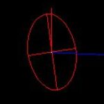
my thing I’m caught up with is how to use the LLH from someone else in a grid only TBC. Essentially calibrating in TBC. I get the concept and the steps by somehow I always am off by .50-.25. Lee Green suggested I wasn’t including enough decimal places when I entered my LLH ( makes sense ). I will try again and get back to you all. For now I just told the surveyor we need an incline plane calibration for our machine so he sent it over and I occupied it and we hit the control very good! So no worries for this project but I’m sure that learning how to build an inclined plane calibration from LLH and NEE in tbc will help me in the future. Thanks for all the replies everyone. Also there is a way to embed a sub-grid of a geoid into a .cal machine file and also into the GCS900. I’m still researching it but I will make a write up when I got it figured out.
Don’t forget that you can always request a site calibration report from the surveyor and just plug the parameters in yourself. You could define it in the Coordinate System Manager and keep it right there in your library for the duration of the project.
TBC’s reports detail all point pairs, and stick the H/V parameters plus a summary right at the top:
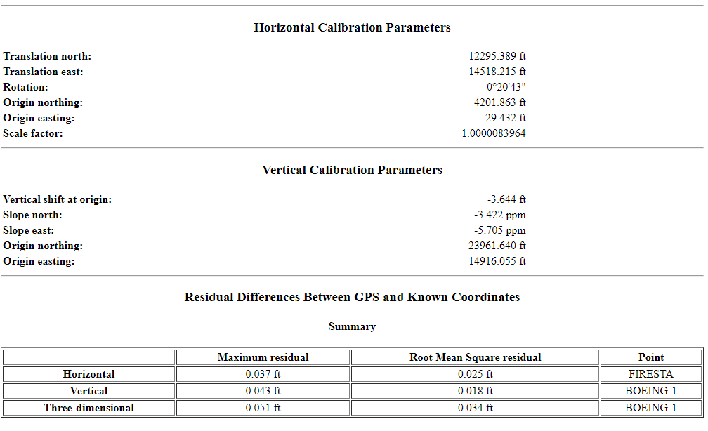
This would also help you chase down any rounding/decimal place errors while you’re working it out yourself.
“…people will come to love their oppression, to adore the technologies that undo their capacities to think.” -Neil Postman

Log in to reply.