
Activity Feed › Discussion Forums › Photogrammetry, LiDAR & UAS › Faster accurate terrestrial scanning with survey methodology.
Faster accurate terrestrial scanning with survey methodology.
JSP replied 7 months, 4 weeks ago 9 Members · 45 Replies

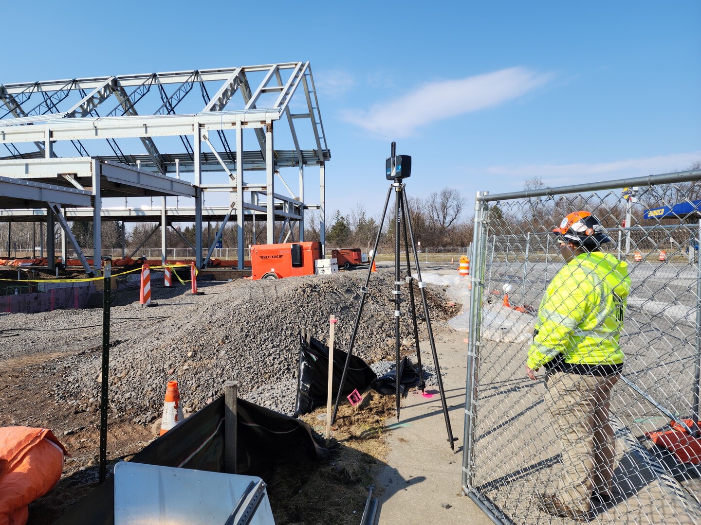
@jitterboogie The dolly would be good on flat surfaces with a survey tripod. We currently use survey tripods, with a traverse workflow, in various environments, I’m looking at high speed scanners and thinking, how can I adapt a carbon fibre tripod used by scanners like Faro, Lieca RTC360 and Riegl, to our current workflow, for fast repositioning, without sacrificing accuracy or benefits of using a survey tripod? One of the problems with light weight carbon fibre tripods is the legs fall through grid mesh, thick rubber pads prevent that, but it’s just another thing that slows down the workflow. It’s a bit like a time and motion study, in order to be fast, slower tasks need to be eliminated. Our registration process if fast and reliable, it’s in the field where we are slow (relative to typical laser scanner workflows, eg RTC360), but we are accurate.
We have thoughts about using the Topcon GLS for control scans, as we know we achieve very good accuracy, then infill using another scanner eg a Leica RTC360 and align the Leica scans to the control scans. But then we’ve got a Topcon scanner sitting there that can do scans in 1:45 seconds and I’m thinking how I can use it too, and was thinking about tracking scan positions using a total station, in a resection workflow, so we don’t have to leapfrog the scanner. If the environment doesn’t support cloud to cloud registration, then we use levelling, resection with least squares, we need to mark out our scan positions and measure instrument height.
If we just want something that imitates, VIS and IMU functionality for pre registration, then we don’t need to record instrument height and level, we can measure the scan position with a total station.
But then, I’m also having thoughts about other scanner workflows.
Everything has compromises, and trade off’s.
Survey Tripod:
Sturdy, good for alignment over a point, comes with various attachments for different ground conditions, eg stars, dolly’s. Good for traverse workflow, not fast for repositioning, ie the instrument is removed from the tripod before repositioning.
Light weight scanner tripod:
Light, fast and easy to relocate, limited accessories for tripod feet attachment, points not easily driven into the ground like a survey tripod, accessories shouldn’t interrupt the workflow. Not easy to position over a known point, most don’t have a plummet aperture.
Can the scanner tripod (really a camera tripod with some mods) be improved?
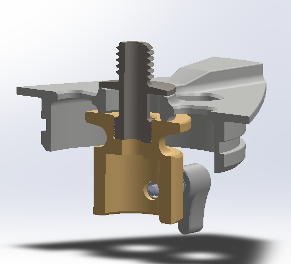
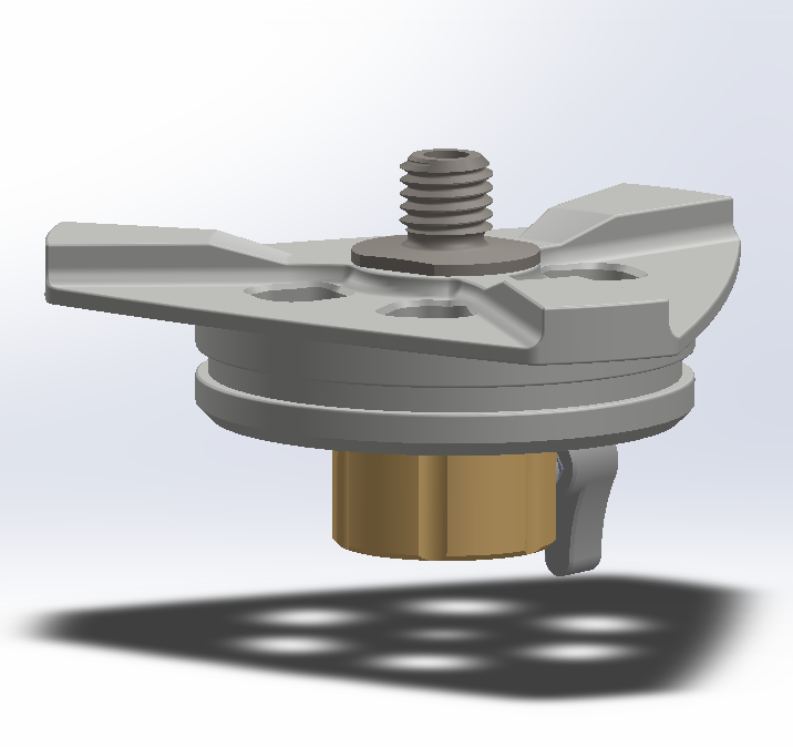
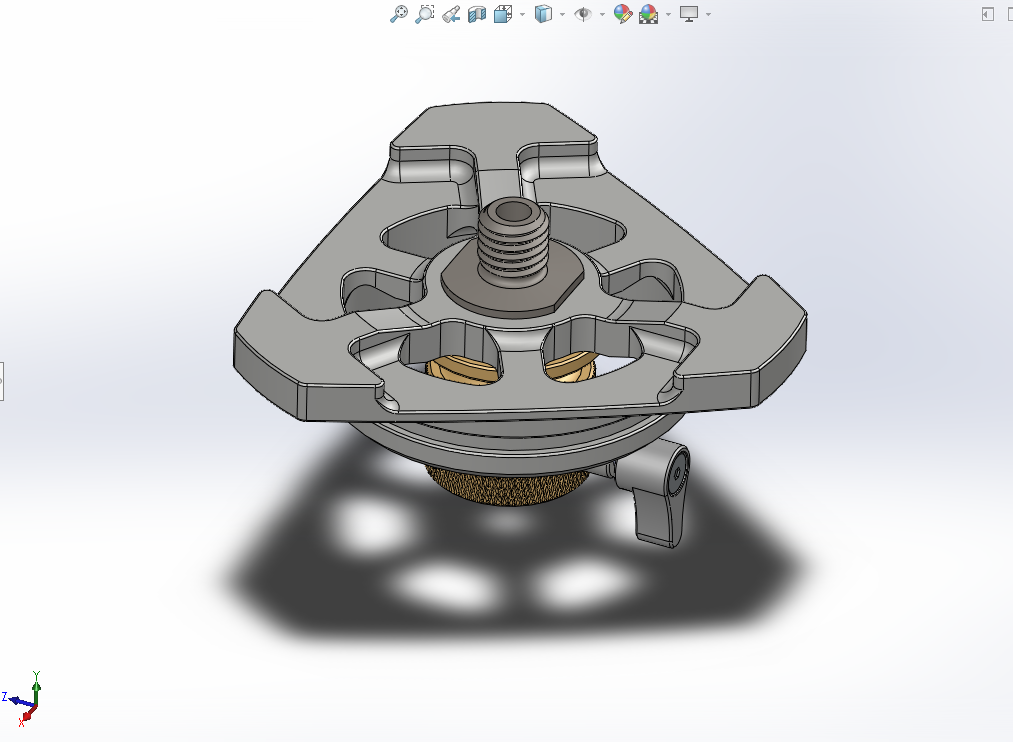
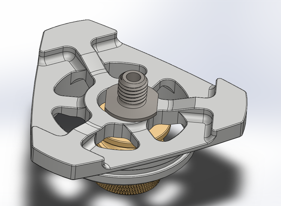
Current iteration of a carbon fibre tripod head, to allow positioning over an existing point, allows attaching a prism, laser plummet for rough marking scan positions for levelling (only accurate if tribrach is aligned colinear), or pre positioning over a point and tape for measuring instrument height. The 5/8-11 screw is hollow, to allow accurate instrument plummet fine alignment (with prism removed):
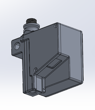
Current iteration of instrument height measurement tool, a 2m tape measure with cross laser plummet:
Cheers,
Peter.
I’m not confident we could completely eliminate the use of the Topcon GLS with a Riegl yet, maybe we can, it is very fast, but we’ll need to achieve similar accuracy to current methodology, we could definitely utilise both scanners. It’s a no brainer if you’re currently using other scanners that rely on targets or cloud to cloud alignment to upgrade to Riegl’s new scanner.
Honestly, I won’t know how accurate the Riegl is until we try it and compare it to our existing results. Some of the specs are a little outside some of our customers tolerances, but as they say the proof of the pudding is in the eating, some of Topcon’s specs are also outside of tolerances and we’ve found ways to address them.
For example, we have to apply filters to the scans to remove outliers to tighten point standard deviation (3mm standard), a 3mm standard deviation, is 6mm sigma at 95% confidence, we don’t only rely on the scanner’s measurements alone, we use a level and total station with least squares. It’s possible to use the Topcon GLS without level or TS, whilst still using least squares, but then we’re completely reliant on the GLS for scale, so we could have unidentified scale errors stacking up over distance. If we use the GLS on it’s own without least squares, then some visible misalignment will be evident in registration results, however Topcon doesn’t recommend using the instrument on it’s own, their standard workflow includes a total station.
Riegl specs:
http://www.riegl.com/uploads/tx_pxpriegldownloads/RIEGL_VZ-600i_Preliminary-Datasheet_2022-11-17.pdf
3 axis magnetometer (compass), that’s cool, I can see how that would be used to pre align scans so they’re all rotated into the same direction. That’s a lot better than the tubular compass the Topcon has, the user can manually orientate the scanner azimuth 😉 I like the barometer, it means the scanner is doing automatic atmospheric correction, we have to do this manually with the GLS and TS.
This sounds interesting (I don’t know what it is) “Waveform Data Output (optional) providing digitized echo signal information for specific target echoes”
I know that GNSS RTK vertical accuracy isn’t wonderful, but RTK will prevent the registration from drifting outside of a certain tolerance, eg if scanning a long conveyor run, it’s not uncommon for typical laser scan registrations to curl upwards in elevation, or add horizontal curvature between control points, the latter RTK will mostly address.
10 second angular accuracy, Riegl doesn’t mention a dual axis level compensator, so it could be 10 seconds. The Topcon has 3 second accuracy for prisms, and 6 second angular accuracy for the point cloud, with a 1 second dual axis level compensator.
One major customer requires 5mm absolute point accuracy, it’s very difficult to achieve, other customers want the same if we can achieve it.
Registered point clouds can appear to have no misalignment, but there can be scale, or curvature differences from reality.
I haven’t tried any of the Riegl range of scanners yet, I’m keen to hear about features that aren’t published:
Can occupy points?
Does it have a plummet?
What type of targets are used?
How are scans geolocated?
Will it scale a point cloud when using RTK?
An accuracy example: A customer asks for scans of a long conveyor, at our best accuracy, we’ll use static post processed GNSS (Auspos) at both ends (up to 7 days of static observations for elevation for at least one point (<8mm @ 95%), 48 hours for northings and eastings (<4mm @ 95%), traverse it with a total station and level, then scan it, with least squares adjustment of all obs. Our scans are also scaled. The point clouds are uploaded into an explorable virtual world where all points represent state grid coordinates and they may be combined with pre-existing scans, if so a 30mm difference in absolute location would be quite noticeable in areas of overlap.
In the above example, it’s possible to scan from one end of the conveyor to the other with the Riegl, very quickly and hand over the registered scans without much checking and they would be approximately geolocated with RTK GNSS, this would be good enough for most applications and cost far less, and it might not make much sense to the person doing the scanning, but if the customer demands a higher level of accuracy, then we will try to deliver it when they’re prepared to pay for it, we oblige, we don’t always know the reason.
Maybe the example is a road, not a conveyor, or a dam wall, or a pit slope, where the customer wants to measure changes, which might be used to assess stability or other issues, accuracy depends on customer requirements.
I guess in summary, I don’t disagree, but I’m not able to give a definitive opinion until after I’ve tested it, and figured out how to achieve the accuracy requested.
Cheers,
Peter.

I’m not confident we could completely eliminate the use of the Topcon GLS with a Riegl yet, maybe we can, it is very fast, but we’ll need to achieve similar accuracy to current methodology, we could definitely utilise both scanners. It’s a no brainer if you’re currently using other scanners that rely on targets or cloud to cloud alignment to upgrade to Riegl’s new scanner.
Honestly, I won’t know how accurate the Riegl is until we try it and compare it to our existing results. Some of the specs are a little outside some of our customers tolerances, but as they say the proof of the pudding is in the eating, some of Topcon’s specs are also outside of tolerances and we’ve found ways to address them.
For example, we have to apply filters to the scans to remove outliers to tighten point standard deviation (3mm standard), a 3mm standard deviation, is 6mm sigma at 95% confidence, we don’t only rely on the scanner’s measurements alone, we use a level and total station with least squares. It’s possible to use the Topcon GLS without level or TS, whilst still using least squares, but then we’re completely reliant on the GLS for scale, so we could have unidentified scale errors stacking up over distance. If we use the GLS on it’s own without least squares, then some visible misalignment will be evident in registration results, however Topcon doesn’t recommend using the instrument on it’s own, their standard workflow includes a total station.
Riegl specs:
http://www.riegl.com/uploads/tx_pxpriegldownloads/RIEGL_VZ-600i_Preliminary-Datasheet_2022-11-17.pdf
3 axis magnetometer (compass), that’s cool, I can see how that would be used to pre align scans so they’re all rotated into the same direction. That’s a lot better than the tubular compass the Topcon has, the user can manually orientate the scanner azimuth 😉 I like the barometer, it means the scanner is doing automatic atmospheric correction, we have to do this manually with the GLS and TS.
This sounds interesting (I don’t know what it is) “Waveform Data Output (optional) providing digitized echo signal information for specific target echoes”
I know that GNSS RTK vertical accuracy isn’t wonderful, but RTK will prevent the registration from drifting outside of a certain tolerance, eg if scanning a long conveyor run, it’s not uncommon for typical laser scan registrations to curl upwards in elevation, or add horizontal curvature between control points, the latter RTK will mostly address.
10 second angular accuracy, Riegl doesn’t mention a dual axis level compensator, so it could be 10 seconds. The Topcon has 3 second accuracy for prisms, and 6 second angular accuracy for the point cloud, with a 1 second dual axis level compensator.
One major customer requires 5mm absolute point accuracy, it’s very difficult to achieve, other customers want the same if we can achieve it.
— attachment is not available —
Registered point clouds can appear to have no misalignment, but there can be scale, or curvature differences from reality.
I haven’t tried any of the Riegl range of scanners yet, I’m keen to hear about features that aren’t published:
Can occupy points?
Does it have a plummet?
What type of targets are used?
How are scans geolocated?
Will it scale a point cloud when using RTK?
An accuracy example: A customer asks for scans of a long conveyor, at our best accuracy, we’ll use static post processed GNSS (Auspos) at both ends (up to 7 days of static observations for elevation for at least one point (<8mm @ 95%), 48 hours for northings and eastings (<4mm @ 95%), traverse it with a total station and level, then scan it, with least squares adjustment of all obs. Our scans are also scaled. The point clouds are uploaded into an explorable virtual world where all points represent state grid coordinates and they may be combined with pre-existing scans, if so a 30mm difference in absolute location would be quite noticeable in areas of overlap.
In the above example, it’s possible to scan from one end of the conveyor to the other with the Riegl, very quickly and hand over the registered scans without much checking and they would be approximately geolocated with RTK GNSS, this would be good enough for most applications and cost far less, and it might not make much sense to the person doing the scanning, but if the customer demands a higher level of accuracy, then we will try to deliver it when they’re prepared to pay for it, we oblige, we don’t always know the reason.
Maybe the example is a road, not a conveyor, or a dam wall, or a pit slope, where the customer wants to measure changes, which might be used to assess stability or other issues, accuracy depends on customer requirements.
I guess in summary, I don’t disagree, but I’m not able to give a definitive opinion until after I’ve tested it, and figured out how to achieve the accuracy requested.
Cheers,
Peter.
Not going to reply to all your remarks but a Riegl is a survey grade instrument. I have done hundreds of projects with it, engineering and architectural.
Long before anyone was building scanners (and certainly Topcon) Riegl was at it. You can scan and use tiepoints with special reflectors to control everything. Also a Riegl can do resection, orientation,… setups and even scan prisms (if further then 200m).
Get in contact with Riegl Usa, they will give you all the details. I’m just a user but a happy one.
If i would need a new scanner it would be a 600i for sure. Riegl is years ahead of the competition, they did on site reg already five years ago, they can take pictures while scanning.
Also a Riegl can do resection, orientation,… setups and even scan prisms (if further then 200m).
Now there’s an interesting feature.
I understand you’re a satisfied user, you seem like a decent fellow, I’m just trying to achieve a higher level of accuracy than normal.
Riegl also allows users to write programs in Python, so potentially it can be customized. Maybe there’s potential for it to communicate with a robotic total station controller tracking it? Then it could use a prism backsight, which should provide good angular alignment. It would need an accurate dual axis level compensator, then we mark scan locations, measure instrument height and later level. I know this would slow the workflow, but not too much, as it would only be necessary for control scans. 10 arcsecond angular accuracy is a bit on the low side though, however the instrument might have a higher accuracy when measuring prisms and trimming the point cloud at a radius might address that. For example a Trimble SX12 is a one arcsecond total station, but a 5 arcsecond scanner.
In any case we could set out a few control scans and fill it very quickly with the Riegl, then fine align it.
Thank you, you’ve given me some information I didn’t know and more questions to ask, which is always a good thing when problem solving.
Cheers,
Peter.
A comparison of scanner accuracy (including scanning total stations). Please feel free to add information, or correct any errors.
Some observations:
- The slowest are the most accurate.
- Riegl is the fastest, it’s angular accuracy is better than other high speed scanners.
- Trimble TX8 has an accurate dual axis level compensator, but angular accuracy isn’t as good as I’d like. This scanner lacks field pre registration, it does have good mixed pixel filters.
- Recent high speed scanners have pre registration and other features to assist registration.
- Riegl differentiates it’s scanners with stray pixel filters & capturing of several pulse returns, speed / distance, where longer distances have slower speed. It also has plenty of sensors to assist with registration. It will be interesting to trial.
Scanner / Total Station
Leica MS 60
Trimble SX12
GLS-2000
TX8
X7
Riegl vz600i
Z+F 5016
RTC 360
Level compensator accuracy
0.5 arc seconds
0.5 arc seconds
1 arc second
1 arc second
3 arc seconds
10 arc seconds ?
14.4 arc seconds
18 arc seconds
Closest Range
1m
900mm
1m
600mm
600mm
500mm
300mm
300mm
Max Range
1000m at 1 point per second
60m at 30,000 points per second
600m
500m
340m
80m
1000m at 150,000 pps,
220m at 2,200,000 pps.
365m
130m
Max speed points per second (higher speeds allow faster high resolution scans)
30,000
26,600
120,000
1,000,000
400,000
2,200,000
1,000,000
2,000,000
Surface noise, standard deviation (either side of mean)
3mm @ 30,000 points per second.
1mm @ 1,000 points per second
2.5mm @ 300m
1.5mm @ 200m or less
3.5mm from 1 to 150 metres.
<2mm from 1.5 to 100m
2mm
3mm, 1mm with extended scan time
<1mm + 10ppm / m
1mm + 10ppm / m
Angular accuracy (arc seconds) standard deviation (either side of mean)
5
6
16.5
20
10
14.4
18
Angular accuracy to prisms (arc seconds) standard deviation
1
1
3
Std deviation point position error at 100m due to angular accuracy
2.5mm
3mm
8mm
10mm (beyond max range of 80m)
5mm
7mm
9mm
Pre registration
No
Yes
Yes
Yes
Yes
Concurrent HDR photography while scanning
Yes
I’ve had a chance to discuss the new Riegl vz600i with the local dealer here in Australia. To achieve the stated 3mm @ 50m or 5mm @ 100mm accuracy, the user needs to set up at least 5 targets as control points, these would be positioned over points measured by a total station and level, with least squares adjustment. The scanner will use its sensors for rough alignment, with 40% to 60% overlapping cloud to cloud alignment using features in the point cloud for fine alignment.
While Riegl has a feature to position the scanner over a point, it’s not recommended due to the instrument’s 10 second angular accuracy, instead, the accuracy stated is achieved using control targets.
Clearly Riegl makes a very fast scanner, I’m told it also produces very clean point clouds due to its time of flight and waveform analysis and it can have good accuracy, when using control targets. Also long range points don’t need to be removed, like some scanners. I’ve had to remove points outside of 50m for some scanners, as they produce a rough surface, that doesn’t mesh well (due to lower accuracy at distance).
Also I asked about the possibility of scanning bolt connection details in high resolution, he advised that it was not a good idea, as the laser diameter would be 3mm, measuring a point spacing of 1mm isn’t going to provide the necessary accuracy. This is a job for a Surphaser scanner or Leica MS60 scanning total station.
I was advised that there is still a place for the Leica P series, Topcon GLS and Scanning Total stations, in natural environments where there’s insufficient detail for cloud to cloud alignment, or when scans are spaced far apart without overlap, sometimes low resolution data is just easier to process, when large amounts of data isn’t required. In this case a Riegl would need to rely on control targets alone for accuracy, and more would be required. While it does have an impressive array of sensors, these don’t provide the same accuracy as control targets, however it does provide RTK levels of accuracy, and that may suffice, depending on requirements, eg, if absolute position isn’t critical and it might be suitable if only a few sparsely placed scans are required.
Where the Riegl will shine is in environments with lots of planes and features for cloud to cloud alignment. Note that there’s cloud to cloud alignment and there’s cloud to cloud alignment, some manufacturers do a much better job than others.
I think the average surveyor is aware of the accuracy and limitations of different classes of survey equipment. This situation is no different.
I think we could classify these different types of scanners under two categories:
- Sensor enhanced pre-registration cloud to cloud alignment workflow requiring overlap.
- Survey workflow: resection, traverse, or occupation with back sight.
I’m working on a carbon fibre tripod setup that will speed up the workflow’s of Leica P series, Topcon GLS scanners, or Trimble TX6, TX8 series, using a Total station to track the position of the scanner, with angular alignment provided by a target, also tracked using the total station. These will not be as fast as a Riegl, but still have their place.
I hope this provides some clarification, please feel free to point out any errors or omissions, or share your thoughts.
In an upcoming job, our client has recent scans of their mine wash plant, not geolocated, we’ve been asked to geolocate them. I find this quite a lot, clients are given scans but know little about their accuracy. Often client expectations of accuracy are significantly tighter than real world results.
This mine site has a permanent GPS reference station (Geodetic antenna with a ground plane), last year the client had 20 days of observations, processed using AUSPOS (Australia’s version of OPUS or ), then averaged, suggesting a 6mm elevation window with a 95% level confidence (3mm std deviation), we’re planning to obtain our levels, by sighting the antenna reference using an Optical level from another building, we’ll transfer that down to deep seated survey references at ground level.
We’re also planning to do a number of 24 hour GPS observations, post processed using AUSPOS to 4mm Northing and Easting window’s @ 95% confidence (2mm std dev).
We’ll install and network deep seated PM’s using total station and level traverses, then we’ll do some background scans with the Topcon GLS, all observations with least squares adjustments (incl the scanner), and then align the client’s existing scans to these.
The client has suggested they’ll want more plant details later, so we may use a Riegl, a Leica RTC360, or Trimble X7 to fill it in and cloud to cloud register to the GLS scans, where there are suitable features for registration.
When your instruments are calibrated, and you are using multiple instruments, with least squares adjustment, you’ll find any issues with equipment, eg: was it bumped in transit?
There’s nothing worse than using one instrument to do everything, then find out later it had an issue with calibration.
Is it overkill?
Another mine has a stacker, sinking on it’s foundations, their plant has been scanned at least 3 times, none of which are georeferenced. This client doesn’t speak well of laser scanning, so I’ve suggested installing some deep seated permanent references and to monitor it with levelling (I’m not about to suggest something the client has a bad experience with, I know this client, he’ll just say no). Had their scans been georeferenced and levelled to a reasonable level of accuracy, they might have been determined from historical data, how much the footings have sunk, software can give you a nice colour chart indicating differences. The civil engineer’s main concern will be identifying whether there is a weaker subsurface layer, which can shear, and cause a mound to form adjacent to the structure, causing the ground beneath the structure to sink and lay it over.
It really depends on the situation, there are many situations where an RTK drone is sufficient, all are survey grade equipment, each with different levels of accuracy.
A scanning total station is more accurate, but slower than the GLS, which is slower, but more accurate than high speed scanners, which is the right tool for the job? It really depends on the job.
A Leica P30 / P40 is closer to the GLS in accuracy, with a 1.5 arcsecond level compensator and 8 second angular accuracy, with low surface noise (lower than the GLS).
It’s not just the scanner’s accuracy, but the overall accuracy of the entire workflow and the care taken.
In open areas, we don’t require high resolution scans, just accuracy, we can space out our scans, cloud to cloud registration doesn’t work under these circumstances, due to insufficient features, or overlap between scans.
The data size of the cloud is also much smaller.
The workflow I’m proposing (using a robot to track the scanner, with levelling post scanning) will also speed up a Leica P30 / P40 scanner and likely improve accuracy over that scanners standard traverse workflow.
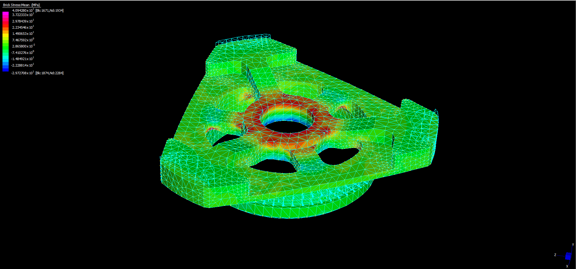
The scanner carbon fibre tripod table adapter for tribrach, following Finite Element Analysis, modelled with 500kg clamping force on the 5/8-11 thread.
FEA Analysis results:
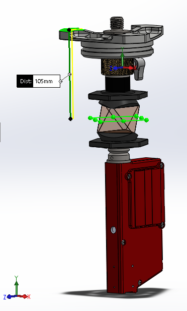
Mock up of Leica MPR122 360 prism with laser plummet instrument height tool (for tracking with robot and levelling post scanning).
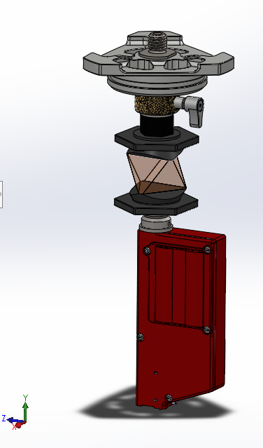
Leica Cyclone classic would be required for this workflow.
Cheers,
Peter.
I’ve had a chance to discuss the new Riegl vz600i with the local dealer here in Australia. To achieve the stated 3mm @ 50m or 5mm @ 100mm accuracy, the user needs to set up at least 5 targets as control points, these would be positioned over points measured by a total station and level, with least squares adjustment. The scanner will use its sensors for rough alignment, with 40% to 60% overlapping cloud to cloud alignment using features in the point cloud for fine alignment.
Clarification, accuracy above is std deviation, or 65% level of confidence. 5mm std-dev = 10mm @ 95% confidence. 3mm std-dev – 6mm @95% confidence.
Adjustment allowance for setting up over a point (can be rough aligned using the laser plummet in the instrument height measurement tool, then fine aligned using the instrument plummet):
@beuckie Do you know if it’s possible to mark scan positions on the ground, does the vz have a laser plummet? We know our scan positions with a high level of confidence and mark them out, it’s easy for someone to set up a total station over a point later and use them when setting out. Some jobs are part of pre project planning in existing industrial plant, new installs and upgrades need to fit in with old plant, some things get removed, but other components remain, a lot of the existing plant gets obscures visibility when setting out.
A Riegl has a plummet although never used. It also doesn’t have to be level so the plummet is rather useless. It’s doable but the scanner is heavy (vz400i) so sliding a tribach on a tripod isn’t as easy. Also there is no levelling bubble visible in the software so you would rely on the tribach itself.
I suggest you get a real live demo in the field where you check it out. No need and useless imho to mention all sorts of figures. The data tells all the values.
If you want some data, sent me an email on lieven (at) lsbbvba.be and i’ll send you some

With my Faro Focus S150+ and SCENE software I use a fixed 2m GPS tripod (carbon fiber). This has the center pole with bubble that allows us to setup the scanner on a nail with a fixed height. SCENE Software will use the scanner position as the highest weight over an targets.
@beuckie Thanks, I’ll take you up on your generous offer. Talking to my local rep, Reigl doesn’t recommend setting up the instrument over a point, which makes sense, it doesn’t have sufficient level compensation accuracy, the tripod would need to be levelled first using a precision carrier, but then the instrument is heavy, so the weight might alter level, so not a good idea, instead control targets are recommended to establish the level plane (at least that’s what I’ve been told, I haven’t used the scanner).
Regards,
Peter.
@leegreen There was a problem you were solving here, as your method is relatively unique, I’d be interested to hear more about your workflow and why you developed it.
Cheers,
Peter.
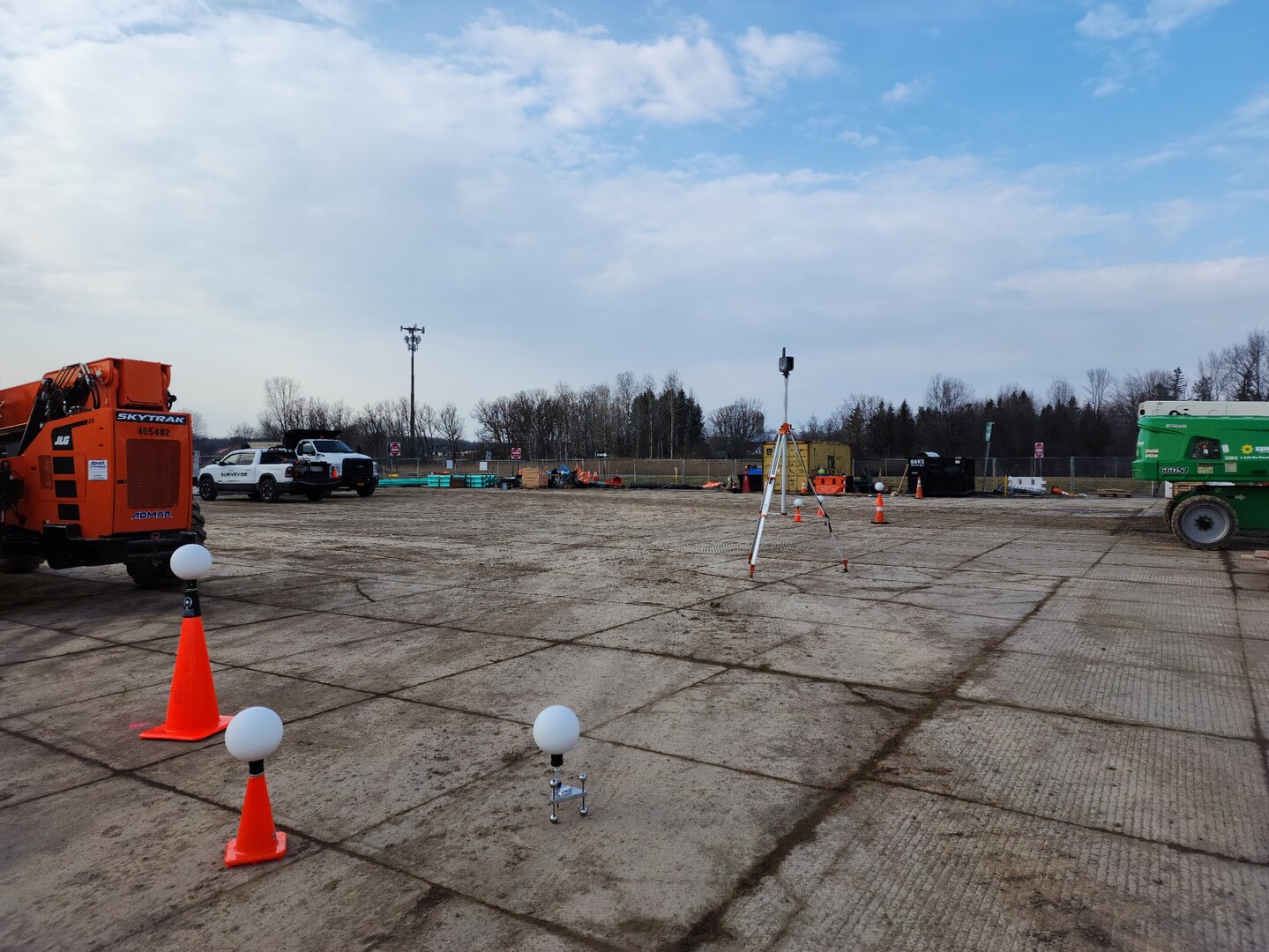
While working on vertical construction sites (BIM) over the past few years, I noticed a new trend where many non-surveyors are performing scans. All were performed without asking for a single control point. Then when their scans don’t align they come to the surveyor. So I purchased a Faro Scanner as this was/is the most common scanner I see on job sites being used by others. In my self-learning and conversations with FARO developers, I noticed that SCENE can use the scan position as a weighted target (control point). It is used as the highest priority. Although we currently can’t user-define the weighted value in Scene, I believe that with my discussion with developers, it is coming. However, the next question was “How do we set up the FARO scanner over a point precisely, with an easy-to-measure height, while keeping the scanner up high“? With the industry standard lightweight camera tripod, this is impossible, plus this flimsy tripod is very unstable in outdoor conditions. So while thinking outside the box I started using my GPS 2m tripod with the FARO scanner. The aluminum tripods are a bit heavy and baulky. Then I found the all carbon fiber 2m tripod from survey pro-USA. This is much lighter, making it easy to level the scanner over a control point, while being very stable. I also learned that SCENE needs at least three “checks” (for lack of a better term) in order to register between two single scans. These three “checks” can be comprised of any of the following: Scan Position, Tilt Sensor, Sphere, Targets, Planes, etc. The FARO does have a compass, and GPS as “check”, however, they are not to be used for accurate positioning, rough only. Therefore I noticed we can use two Spheres and the Scan position (with tilt as backup) or at the very least we can use tilt, scan position, and a single sphere.
Here is a pic of my common sphere configuration between scans, along with 13ft tripod setup. Notice the shortest sphere is on The Marksman This allows me to accurately and easily set up the Sphere over another known position such as nail or cross cut. Helping to strengthen the registration.
@leegreen So you’ve basically got control scan positions, with rotational alignment determined between scans by spheres, which doesn’t require measuring numerous target locations and provided your control points are relatively tight (least squares adjusted), you avoid the lack of loop closure that Scene has, which leads to registration problems, and you don’t have to register all your scans at the same time, once you have a network of aligned scans to your control points, they should have accurate rotational alignment. I see you’ve got the Ricoh Theta camera on top, so you’ve got short scan times too.
Be careful with Faro’s going out of calibration, I’m guessing with your workflow, you’ll likely be able to tell when the scanner is starting to drift outside of calibration tolerances.
Cheers,
Peter.
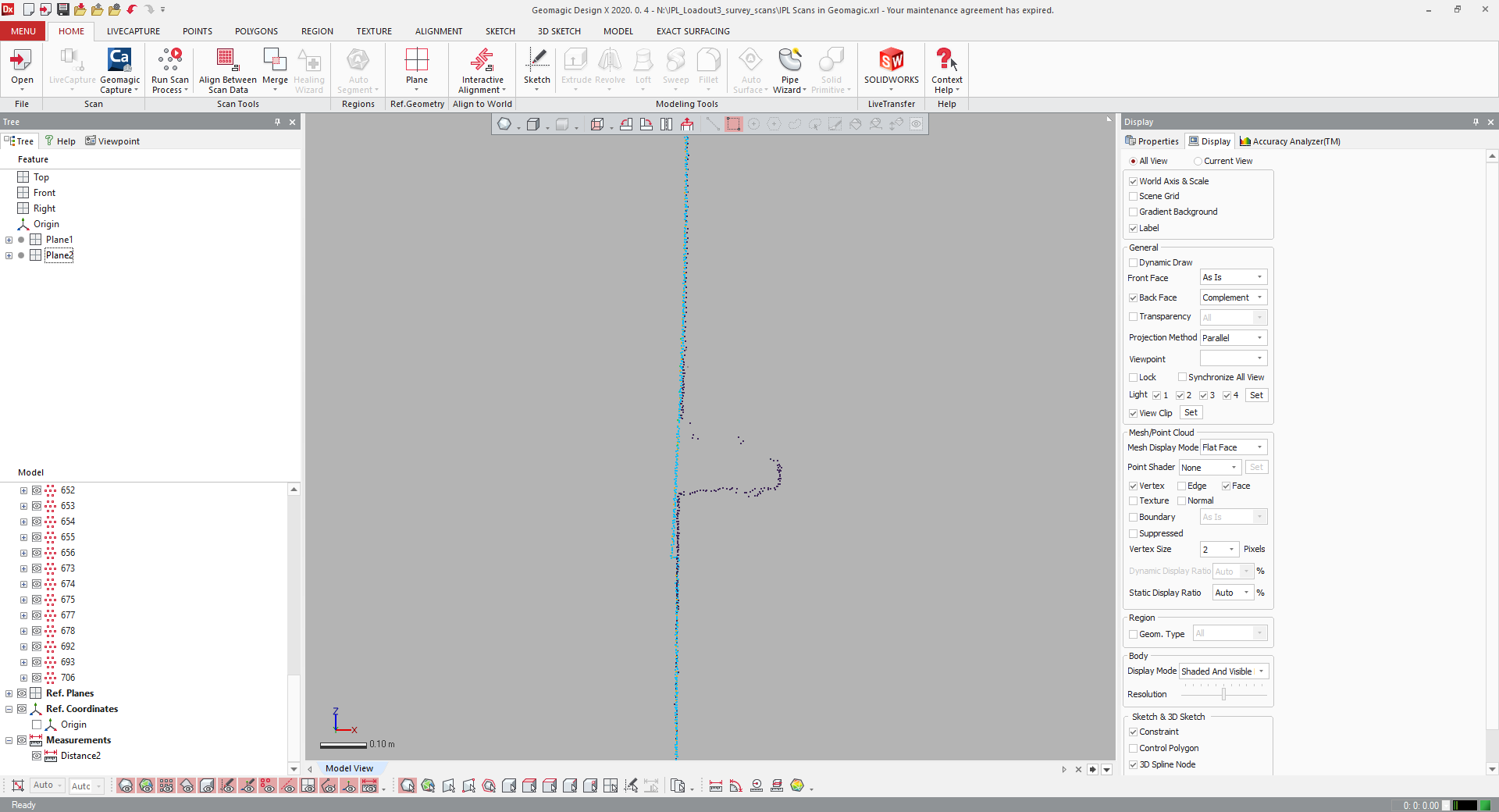
Just posting some images here, so people understand the level of accuracy and precision we want to achieve I have not yet seen cloud to cloud alignment that achieves the same, I would be pleased to be proven wrong of course, if someone can produce some scans the prove otherwise.
This is wall sheeting, scanned inside and out, the scans inside and outside the shed are not in a line of sight of each other.
Horizontal and vertical slices through wall sheeting, showing overlapping sheets:
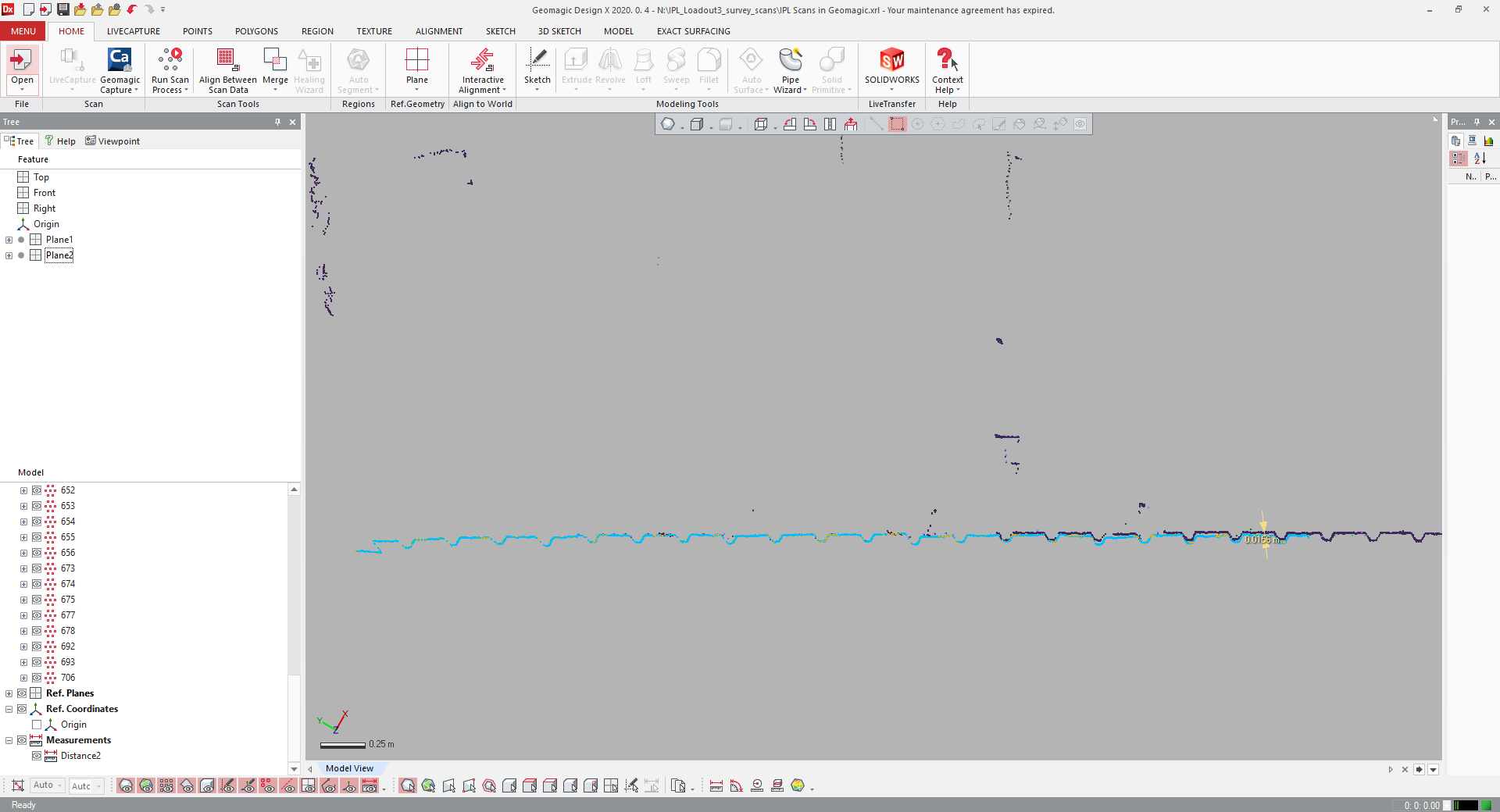
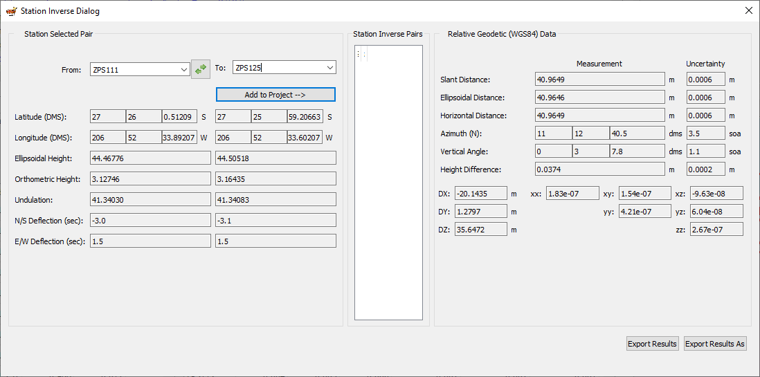
The level of uncertainty between scan positions:

Another section of wall sheeting:
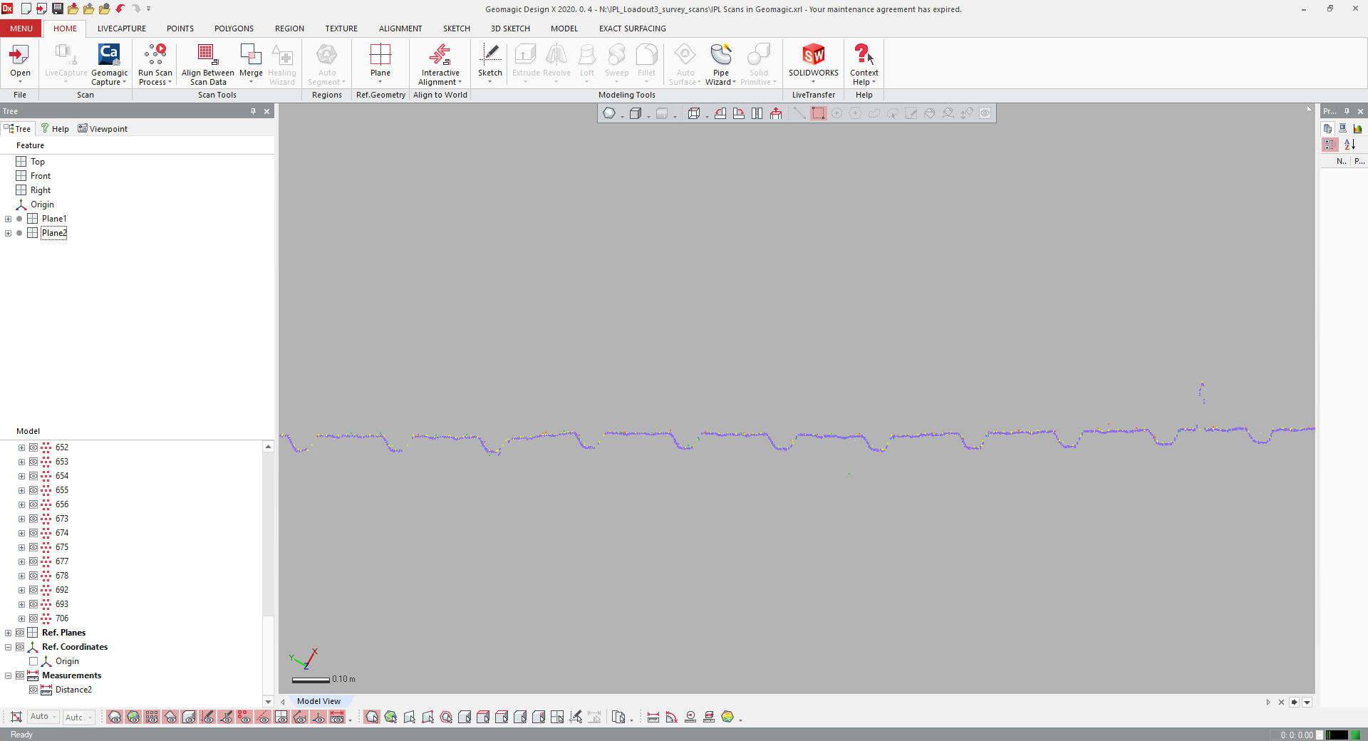
Uncertainty between scan positions:
More to follow.


Log in to reply.