
Activity Feed › Discussion Forums › Strictly Surveying › How to Inverse Between Points with SPCs
How to Inverse Between Points with SPCs
Posted by field-dog on June 1, 2023 at 1:27 amI want to calculate a distance and bearing between the two points posted above. I don’t want to use any software on the NGS website because I want to learn how to do it manually. Can anyone provide me with any good documentation on how to do that? My office wants to RTK the two points and compare that data with the record data. The entire project we’re doing will be referenced to the center of section line defined by the points.
bill93 replied 10 months, 4 weeks ago 10 Members · 25 Replies- 25 Replies

Are you wanting a grid inverse from the spc ? If so distance is equal to north – north squared plus east – east squared add take square root. Make yourself a sketch all north and east are is distance from an origin all right triangles. Just distance north and east. Bearing is the old sin cos tanjent. So plot it out and look at the given opposite /adjacent arc tangent. Etc. Remember to convert from decimal to dms. Now the sketch is important as it will help you visualize the quadrant so you will know when to add or subtract 180 etc. all bearings have to be less than 90. Hope this helps. If you want to to geodetic inverse from lat and longs a little different and i don’t think i could type that here on my phone. When doing geodetic inverse forward and backwards is usually in azimuth form so not bearing. Also the forward and backward azimuth will be close but not exactly 180 degrees difference. The distance is a mark to mark not horizontal if my memory serves me correctly its been a minute. On the grid inverse its just like the same math you did in school x and y. The quadrants are different numbers for us land surveyors vs say physics and academic math. Just draw the pictures use your diffence in north and east as part of the triangle. And once you do a few you will have it down. Bearing is just a angle. Knowing which one is key. Plot a line. Use sin and cosine to compute lat and departures go and add the north and easting to the lat and departures. You will quickly see its all a right triangle in simple terms. If you get it down and use a hp you can learn to speed up the process by rectangular to polar key. Get it down first then use the hot key to do distance and bearing.

Are you wanting a grid inverse from the spc ?
I’m still trying to get all my SPC and geodetic nomenclature straight. I guess if you’re comparing what’s on the ground (plat corners and property corners) to fractional corners on the ground (CCRs, like above) you’ll need to use the convergence angle, scale factor, and zone, right? You say those are applied to the difference of the latitudes and the longitudes between the points?
MH
Here’s an excerpt from a manual I studied for the PS on geodetic calcs with answers. This was “fun”, but ultimately didn’t show up on the test I don’t believe. For your question, particularly from #62.
https://1drv.ms/b/s!AthiBVG7hA7Ng4BaDKfte0uVX26wDQ?e=E7P96p
ddHere’s an excerpt from a manual I studied for the PS on geodetic calcs with answers.
I signed into Microsoft OneDrive, but 99% of the text is missing. Maybe I’ll have better luck on my home computer.
MH
My office wants to RTK the two points and compare that data with the record data.
Tie points with enough redundant & independent observations to meet minimum relative accuracy specs. Use the measured grid bearing for the basis of the survey and note the record bearing per the CCR published positions. Done.
If you really, really want to compute geodetic to SPCS conversions by hand, NGS NOS 5 will get you everything you need (and more).
Grid computations are pretty easy and plenty rigorous enough for most projects, which is why they are so popular. Square root of the sum of the squares of the differences between northings & eastings will get you the distance. Arctangent of the difference in eastings divided by difference in northings will get you azimuth. Done.
The difference between the convergence/mapping angle of those two points is only ~2″ (nearly same longitude), so the difference in the forward/backward geodetic bearings is minimal.
“…people will come to love their oppression, to adore the technologies that undo their capacities to think.” -Neil Postman
It appears the scale given on the county data sheets is actually the combined scale factor. So grid inverse x (1/0.9999791) = ground inverse. About 0.10 ft more. Of course for RTK observations that’s almost an irrelevant exercise.


geodetic is negligent
How irresponsible of it.
I agree it is negligible at low elevations and moderate distances unless you are going for high precision at a point on the projection where the map is being stretched a lot (SF).
.Use the measured grid bearing for the basis of the survey and note the record bearing per the CCR published positions.
Thanks for this. It’s like gold to me.
If you really, really want to compute geodetic to SPCS conversions by hand, NGS NOS 5 will get you everything you need (and more).
Thanks for the link. I would hate to be labeled a “button pusher.”
MHHere’s an excerpt from a manual I studied for the PS on geodetic calcs with answers.
I signed into Microsoft OneDrive, but 99% of the text is missing. Maybe I’ll have better luck on my home computer.
Maybe it’ll just stick here:
dd
A surprise or two here:
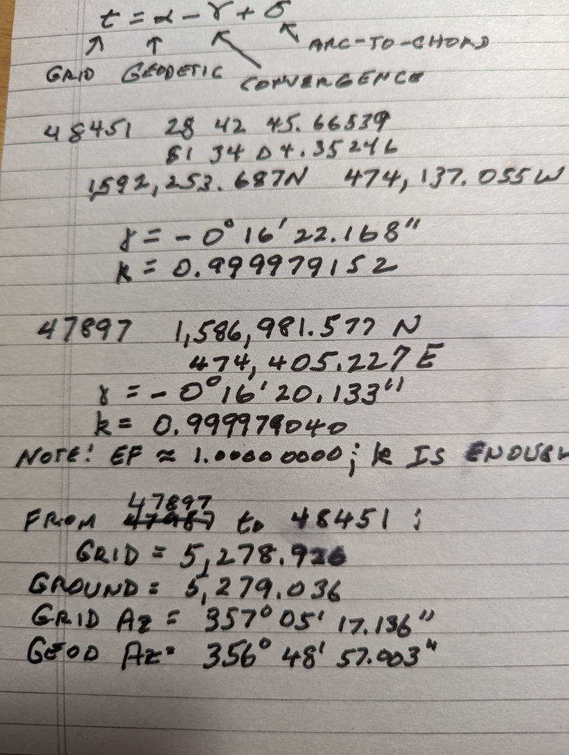
Biggest surprise is its within a foot of 5280.
@field-dog ok so grid state plane coords are just plane coordinates simple math. Not necessarily geodetic. Only time a extra step comes in for computations is for ground to grid distance or grid to ground distance . Unless you want to get into the weeds and start considering things like deflection of the vertical etc. grid bearings are just the simple math. The convergence angle is to get from grid bearings to geodetic etc. north. True north is equal to astronomical north or some geodetic north. The lines of longitude on a handy desk globe converge at the poles so they are nat parallel like grid bearings. Now i am not in a plss state so i think ask the experts on the 1/4 and section corners. It was prior to the year 2000 when i did sections. If i remember correctly most of those were done via astronomical north. You can still get from grid to geodetic via convergence then geodetic to astronomical via laplace correlation if needed. On very long lines t-T

— attachment is not available —
This is the sort of stuff I like. I was a little disappointed I don’t get to do much of this in the working world since everything is computerized.
In fact, I think the closest I came was when a contractor asked for stakes for a manhole that landed in the middle of an intersection that was tore up and being worked on in all 4 directions. I was staking everything by station and offset but he asked if I could put them in the adjoiner’s yard which mean they would be at about a 45 degree angle to the manhole. I did some math in the truck to calc a couple points and made it work. As a recent graduate in particular that was a cool thing to be able to do.
@field-dog you keep learning. Thats what it is all about. This site is great for this. We never stop learning and as soon as we think we have it all figured out the non flat earth humbles us to learn something knew. A new publication will be released soon nos 92. I believe. I believe they stated at FIG that a alpha version would be released. But I didn’t take good notes unfortunately. I was to busy wrangling kids at pool. But the NGS day had a lot of great information so lots of things going on that will be out for us all to learn.
@field-dog hey on NGS site there are numerous videos presentations on datums coordinates systems etc along with all the publications. It cost you nothing and truly is a great resource. Some you can even take a test and get a certificate for. Some are short some longer. But all of that information is available for the knowledge thirsty folks. When i was coming up i could only read. The different publications and one of my all time favorites was geodesy for the layman. Now you can pop popcorn and watch on a smartphone lol. Just keep learning. The profession needs people just like you who are constantly learning. And wanting to learn. I learn something new all the time. But i am not the brightest pea in the patch. But it’s so much fun. Keep it up.
I believe they stated at FIG that a alpha version would be released.
I wanted to attend some of the classes at FIG, but it was too expensive. Were Carlson and Leica there?
MH@field-dog I was there to support the wife and wrangle kids. I know trimble javad hexagon etc. I imagine carlson and others were there also. But I didn’t go to any sessions except the NGS day one. I was sick the week before and just didn’t register and the kids wanted to play in the pool lol. Maybe next time i will do more sessions. But it was truly last minute for us even going. The wife decided that it would be fun for kids. I was lucky to get to attend ngs day. We got a babysitter that day. Well the wife of a co worker said i know you want to attend some sessions so she watch the girls that day.


Log in to reply.