
Activity Feed › Discussion Forums › GNSS & Geodesy › Yolo Base Line 1881

Fascinating. More, more.
> I have one question on the ice bar. I grasp how they moved the bar forward and used microscopes to exactly position the ends of the bar, but how did they transfer the measurement down to the stone monuments?
I didn’t get the idea that the bars used in measuring the Yolo Base Line were ice bars.
Appendix No. 17 (beginning on Page 341) of the 1880 report of the Superintendent of the USC&GS gives a description of the construction and use of the earlier design of baseline measuring bars, including transfer of measurement to ground mark by theodolites.

base line buggy
If one googles Yolo baseline buggy
You may get to a site that has pictures of the Yolo Buggy.
Very interesting and there is another photo of one of the Yolo towers.
I think it was at bldg.com or something like that.
There is also a nice comment by the historian that engaged Jim F. into the survey investigation.base line buggy
> If one googles Yolo baseline buggy
The Bancroft Library offers this photo of the moveable shade under which the baseline bars were laid out. Note that in the photo the baseline has reached a fence stone and a measurement is evidently being tranferred to it from the bar via the theodolite with the seated observer.
USC&GS Eimbeck Duplex Bar
BTW, here is a link to a description of the next advancement in baseline measurement by the USC&GS the so-called “Duplex Bar” developed in the 1890’s by William Eimbeck (who was one of the personnel involved in the 1881 measurement of the Yolo Baseline.
Note that it dealt with the problem of thermal expansion of the bar by having two bars of different alloys with different expansion coefficients. That made two separate measurements possible from which the temperature could (in theory) be worked out by the relative differences in the lengths of the two bars.
USC&GS Iced Bar
And this link gives a description of an even later development (in 1891-1892) by USC&GS for baseline measurement using bars cooled with ice.
Note that part of the field effort involved building a structure in some convenient nearby location in which to store the large quantity of ice that the baseline measurement would consume.

USC&GS Eimbeck Duplex Bar
> Note that it dealt with the problem of thermal expansion of the bar by having two bars of different alloys with different expansion coefficients. That made two separate measurements possible from which the temperature could (in theory) be worked out by the relative differences in the lengths of the two bars.
The bars used in the Yolo Base Line survey also used two metals — steel and zinc — as a means of compensating for thermal expansion, but in a very different arrangement from the Eimbeck approach. In the former, the bars were riveted together such that the two outer steel bars expanded independently of each other, controlled by the intervening zinc bar. Each bar assembly had only one terminal point at each end. The Eimbeck bar sets, by contrast, used two completely independent tubes — one steel, one brass — enclosed in a metal jacket. Thus each end of the bar set had two contact points.
The zinc bar apparently behaved a little unpredictably in response to temperature changes, and Charles A. Schott, who wrote the report on the base line calculations and the use of the bimetallic bar to the USC&GS Superintendent, didn’t seem to think that the steel-zinc-steel arrangement was well-suited to the task. He suggested that using either a steel-brass-steel arrangement, or a single steel bar with careful temperature regulation, would produce equally good results with less fussiness.
> It purports to show the bars in use, though it would appear to be from a different era judging from the clothing
In fact, I wonder if these might be Eimbeck bars.
> How do the “fence stones” fit present day fences, and (for whatever reason) might these fences ever have been accepted as boundaries? These questions come to mind because on a current project we have a fence location that purportedly dates back to 1873 (but have no “fence stones” to help us prove it!). Multiple contradicting GLO surveys, and lack of evidence today from those surveys, have us looking at the “1873 fence”. I get the feeling that out in the central valley you work in it’s not unusual that there would be a lack of GLO evidence, leaving fences as the best evidence.
So far I’ve only recovered 1 fence stone, and it was a foot or so south of the existing fence, which isn’t very old. I don’t anticipate much use of the fence stones for boundary work, though. While original GLO evidence in this area is pretty thin, most of the PLSS corners that coincide with ownership lines are marked by iron monuments (axles, buttonheads, etc.), some of which have a pedigree and some of which don’t. But with some exceptions, these monuments have been accepted as marking those corners, so the fences don’t really come into play much.
About 15 years ago I was retained to subdivide a 1500-acre ranch in Yolo County that comprised most of 3 sections. It was cattle country, and not real great at that due to lack of water. The entire ranch had been held by the same family since patent. I didn’t find any monuments at the interior PLSS corners, and though the fences — which looked like most old fences in the area — ran roughly along the approximated aliquot lines, the measurement discrepancies were far larger than I expected. Then the owner told me that until the 1940s the entire ranch and some of the adjacent land had been used for dryland grain farming as a single unit, and that none of the fences predated the conversion from farming to grazing. I ended up proportioning in the interior corners, in one case having to go a mile and half north of the ranch to find a reliable monument.
> The more distant original RMs have never been recovered; both are in heavily cultivated fields that may have been ripped. I rate their survival prospects as iffy.
I decided to play hooky this morning and do bit more work on the Yolo Base Line original RMs. Per the 1882 report, 4 RMs were established:

Sketch No. 6 isn’t in the PDF copy of the report I have, so I relied upon the 1931 recovery note from the datasheet for dimensions from the station:

I calculated the locations of all 4 marks last night, and began this morning by looking for the two close-in RMs. The location on the north side falls in a farm road. It might still be there, but the ground was too hard to dig up by hand — I’ll need to go back with a demolition hammer to get through the hardpan. The location on the east side is just north of a fence, and looks encouraging. I probed to about 18″ without result, so that one needs a shovel.
The two more distant RMs fall in cultivated fields, both of which are prepped but not yet planted. I decided to start with the least prominent of the two in order to avoid attracting unwanted attention (I haven’t yet obtained permission to be mucking about in the fields). When I navigated to the spot, the first thing I saw was a chunk of granite sitting on the surface, an ominous sign:

However, probing down about a foot resulted in a solid hit, so I decided to dig. I found the stone largely intact, though clearly damaged:

A little cleanup with a whisk broom showed the stone with leaded copper bolt surrounded by mortared brick, as per the description:
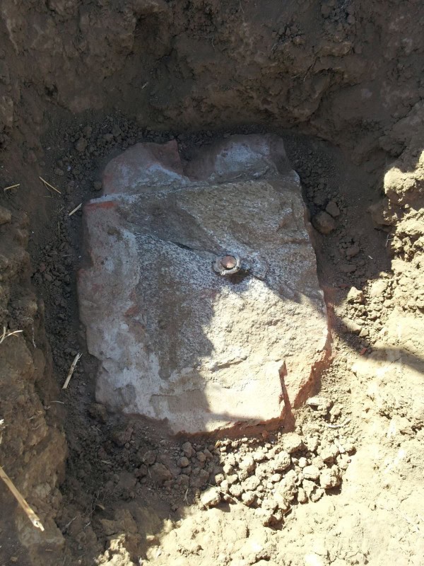
A closeup of the bolt shows that it’s been hit and the top sheared off, presumably during farming operations:

The actual position missed my calculated position by about a foot. I’m thinking the “at right angles thereto” was actually a rough angle, since the purpose of these RMs was explicitly for reestablishing the station in the event that the tower settled prior to completion of observations. Colonna set up on this one, sighted the station mark, then marked the near RM.
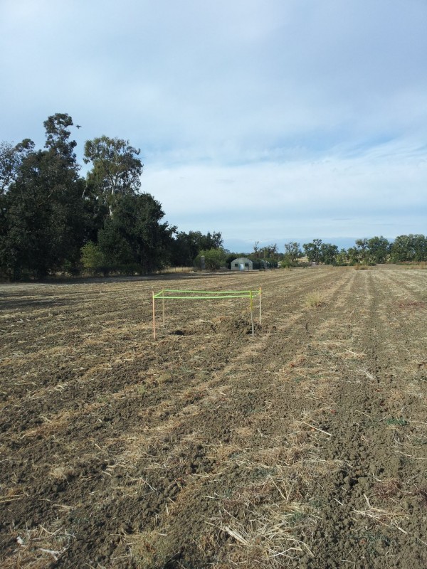
In any case, I recorded a 15-minute shot on it for posterity:


I decided to leave the hole open so the others who are working on this project would have an opportunity to look at it:
However, since I’d now put a hole in an active field and left it open to boot, I figured I’d better come out in the open with the project, so when I got back to the office I started making phone calls. This whole area is part of the UC Davis campus and is marked “authorized personnel only,” mostly to keep out the casually curious; it’s not a high-security area. Although I do a lot of work on campus and am accustomed to driving pretty much anywhere I need to go, the open hole — and a desire to open other holes — made me want to seek formal permission. It took a lot of phone calls before I got someone who can actually do something with it, and I’m hopeful that he’ll end up assisting the project. I need to put together a document he can use to understand where these marks are and what their significance is, so that’s my next task.
:good: :good:
well done!
it seems that you’ve been Penryfied.Nice hole also
was it directly beneath the surface stone?
> was it directly beneath the surface stone?
If by “surface stone” you mean the chip that was lying on top, the answer is no. In the first photo above, the lath is at my calculated position, and the bolt was about a foot to the right of that. The chip is shown right where I found it.
If you mean a surface mark, there wasn’t one. This stone is a reference to the actual station (visible in the distance between the lath and the building), so no surface mark was set.
> > was it directly beneath the surface stone?
>
> If by “surface stone” you mean the chip that was lying on top, the answer is no. In the first photo above, the lath is at my calculated position, and the bolt was about a foot to the right of that. The chip is shown right where I found it.
>
> If you mean a surface mark, there wasn’t one. This stone is a reference to the actual station (visible in the distance between the lath and the building), so no surface mark was set.Ok I meant the chip which appears to a good size chunk to me. It is odd that it is at the surface like that flat.
Will a metal detector pick up the bricks? I get buzzes on bricks sometimes.
> A closeup of the bolt shows that it’s been hit and the top sheared off, presumably during farming operations:
>
>
>
> The actual position missed my calculated position by about a foot. I’m thinking the “at right angles thereto” was actually a rough angle, since the purpose of these RMs was explicitly for reestablishing the station in the event that the tower settled prior to completion of observations. Colonna set up on this one, sighted the station mark, then marked the near RM.It doesn’t particularly make sense, though, that the reference marks wouldn’t have been set at as nearly a right angle to the endpoint of the baseline as possible, does it? I mean, everything else on the survey was apparently done with obsessive care, so why would the reference marks not have been set that way as well? Wasn’t the real purpose of the baseline to fix the scale of the triangulation network that extended from it? That being the case, the rational design for the reference marks would require that they be placed at as nearly right angles to the baseline as possible so that any shifts in the pier that would alter the distance from the other baseline station would be readily measured with a theodolite alone.
Given the damage to the top of the granite block and if it was only 12 x 12 x 12 to begin with, isn’t it more likely that excavating around it more would show that it had been shifted in relation to its foundation?
> I mean, everything else on the survey was apparently done with obsessive care, so why would the reference marks not have been set that way as well?
That’s certainly an argument in favor of Colonna having cranked out a true 90. It’s hard to imagine even the block, let alone the block along with at least one course of bricks, getting moved around horizontally without also getting tumbled and the mortar cracked to some extent, but I suppose it’s possible.
It’s also possible that the published positions of one or both station marks, which I’m using to calculate my search locations, aren’t very accurate. The fence stone I recovered a couple of weeks ago hit within 5 cm for distance, but missed 14 cm for line using those record positions. (That was a 1-minute RTK shot.) The RM stone — using an OPUS-RS position — misses 17 cm for distance and 25 cm for line.
As an exercise, I assume that the near station (YOLO SOUTHEAST BASE) has moved, and that yesterday’s RM is still good. I hold the record distance from the RM to the station, but use the station for line. I then hold the published position of YOLO NORTHWEST BASE to establish the base line. That puts the fence stone within 5 mm of line (though the RTK error is certainly larger than that), but leaves the angle to the RM about the same (about 89°51′).
Lots to play with, but right now it’s more important to recover as many originals as possible and then see what fits. I also plan to get at least a 2-hour static vector on the base line endpoints, though when I’ll be able to do all of this is very much up in the air at the moment.
If anyone wants to play with coordinates, here are the relevant SPC values (NAD83 2011 Zone 2 meters, north, east):
Published positions, from the datasheets:
612353.126 2012296.626 YOLO NORTHWEST BASE
595631.670 2017410.801 YOLO SOUTHEAST BASECalculated positions, holding published and using record angle and distance:
595660.895 2017506.356 RM 2E
597741.205 2016765.610 SEARCH STONE FNCMeasured positions (RTK for the fence stone, OPUS-RS for the RM):
597741.133 2016765.486 FND USCGS STONE
595661.089 2017506.123 FND CU BOLT IN 12X12 GRANITE STONE> > I mean, everything else on the survey was apparently done with obsessive care, so why would the reference marks not have been set that way as well?
>
> That’s certainly an argument in favor of Colonna having cranked out a true 90. It’s hard to imagine even the block, let alone the block along with at least one course of bricks, getting moved around horizontally without also getting tumbled and the mortar cracked to some extent, but I suppose it’s possible.I may have misunderstood the construction of the monument, but I thought it had a wider foundation of two courses of mortared brick that the 12 x 12 x 12 granite block was placed on (presumably in a mortar setting bed) and then surrounded by brick laid with mortar. If the thing is as I’d imagine it to be, there wouldn’t be anything to keep the block from shearing off its mortar bed on the brick foundation other than just the resistance of the soil that the sides of the block contact. It should be easy enough to probe the edges of the brick foundation to see whether the granite block remains nominally centered on it.
I assume that you’ve already checked the pillar for plumbness that the baseline terminal monument sits upon.

@kent-mcmillan Hi there, it looks like your post on the yolo base line is several years old but it was just forwarded to me. You reference photos in your post, but none came through, except the one with seated surveyors (accessed through a link in your post). Do you have other photos? I was a surveying assistant years ago but my more recent interest is as a science/geometry teacher. I love designing lessons based on real life experiences and knowing there’s an important base line in Yolo County is wonderful. I would like to try finding the beginning and end point markers myself. Any help with locating them would be appreciating them, along with photos. Thanks. Camilla

Another base line investigation by Jerry Penry in Nebraska and some discussion on the forum about it. We got off in the mathematical weeds discussing this one after the initial description.
.@camillarumseyhouse-com
Note that Jim Frame was the one who investigated Yolo. Kent McMillan used to get deeply involved in all discussions on the forum but has moved on to other venues.
.A Google search on “yolo base line” will bring up lots of links to photos and some text information. There’s even a Facebook group, though it’s not very active.
The 1882 USC&GS annual report to the Superintendent contains a lot of descriptive material about the Yolo Base Line. I’ve attached the relevant appendix.
Log in to reply.