
Activity Feed › Discussion Forums › GNSS & Geodesy › Propagating error from a GPS localization/site calibration
Propagating error from a GPS localization/site calibration
Posted by HICALS on November 18, 2019 at 6:00 amI am curious how error would be propagated to subsequent control set from a GPS localization/site calibration. The topic recently came up and I wasn’t sure.
Cheers,
HICALS replied 4 years, 5 months ago 8 Members · 14 Replies- 14 Replies

How many points used in the calibration?
.
I will answer that question with a question. How would it not be propagated? Seems to me it’s built into it.


@linebender
I understand the error is built in. The residuals of the coordinates created via the site calibration transformation give an indication of how good the fit is to the monuments calibrated to. My question is how is that error propagated to subsequently set control.
I would assume that the only residuals shown (using proprietary software) from a subsequently set control would be the residuals from the RTK/RTN vectors and not from the transformation itself.
I am not here to judge the merits of this adjustment but rather to gain a better understanding of it.
Cheers,

Most software I’ve had experience with does a few things during a “localization or calibration”. They apply a unique scale, rotation and translation to best fit the given control you measured. Then, after applying those, they display the residuals. Problem with this is, it is only as good as the given control. If the control is junk it will still perform this. If you do not have a solid understanding to take a hard look at the scale it produces you can easily miss feet in error. Example I used was a four point localization. There was about 1.5′ in error placed into it intentionally to show this. We put it in a manor where if you applied a scale of 0.995 it gave great results. So if you don’t understand the scale issue it can easily get out of hand. I refuse to use calibrations. I will shoot everything using the correct ground scale and if need be, I will apply my own translation and rotation. If scale doesn’t work, you have bigger problems of the site not actually being the size people think it is.
I think the only possible response is the default land surveying answer: It depends.
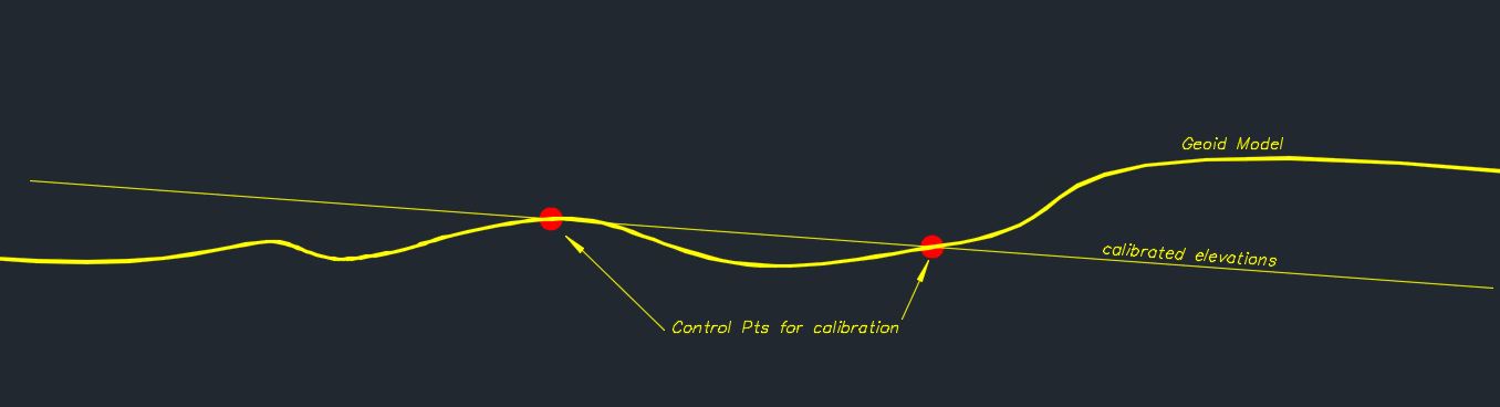
Site size, location and configuration factor in heavily. Lots of grade throughout? Is it unusually large or irregularly shaped? What’s the geoid like in the area? (Are you using a geoid?)
Then you have site constraints and control. Are they evenly dispersed throughout and around the site (including at high and low points)? Do they approximate the general topographic surface, or are you trying to match some legacy control that, while relative to itself, does not really follow?
Then procedures.Can you occupy enough control to really analyze the entire site? What is your error budget?
All of those things, plus observation procedures and adjustment workflow, factor into the amount of error propagation, and even the direction of the error.
Each site is different, and procedure will impact error propagation as much as the site itself.
“…people will come to love their oppression, to adore the technologies that undo their capacities to think.” -Neil PostmanAssuming the following:
- Site is flat
- The scale factor calibration parameter is acceptable for the size of the site
- The 3D residuals are within tolerance for the project
How would the residual errors be propagated to the subsequently set points? Would the RMS residual be calculated and used in addition to residuals from redundant GPS vectors?
Cheers,

If the subsequently set points are located within the bounds of the calibration points then the error in them is going to be a function of the precision of the measurement and the error in the calibration itself. If your calibration points have horizontal residuals at centimeter level and you set control with RTK, you’ll have the centimeter of uncertainty inherent to RTK in the global coordinate, plus the centimeter inherent to the transformation in the local coordinate. Not to imply that those two error sources are in any way linear or additive; they’re completely independent of one another. From my experience, if the grid coordinates that were used to create the transformation are very precise, subsequent points located within the bounds of the transformation are typically also precise with respect to the local control.
However, if you calibrate a site and then go try to set / propagate that site outside the bounds of the grid control, then all bets are off. Errors will extrapolate out and can have a tendency to get real big real quick, especially if the geometry of the transformation was poor to begin with.
I try not to use site calibrations, but sometimes that’s the only good way to be able to use GPS in a plant grid, for instance. If you need to use one, you absolutely need to take the time to set it up correctly, even if that means setting additional control in the local system via conventional means.
Since the two error sources are completely independent of one another, it would seem that subsequent error propagation does not involve a straight forward calculation, but rather being comfortable with both sets of residuals.
For those that use site calibrations, do you also typically tie all the site calibration set points using total stations?
Cheers,
As with most of this stuff, it depends. A typical scenario is that a plant wants you to use their plant grid system but they only have a couple of good monuments and the geometry of them isn’t robust enough to perform a site calibration. One way or another you’re going to have to get good plant control all around the site, and typically that’s going to mean doing some traversing and possibly levelling. It can be done with GPS only, but you better really know how to use your software if you’re going to go that route.
I used to encounter site calibrations a lot more back in the late ’90s – early ’00s when a lot of firms were getting into GPS for the first time. Typically a firm would have a subdivision they were working on that had been established by traverse and levelling and was in a project specific local coordinate system. It was completely common to go out, measure all of the control with GPS, and then calibrate to the site. This almost always worked well because their traverses generally bounded the sites and the control was very accurate. It’s pretty rare that you would encounter a similar situation these days.
As I said, I try to avoid site calibrations, but if someone hands me a bunch of stuff that they want staked out in plant grid, or asks me to provide the points from a survey that was done in SPCS in their plant grid, then a site calibration is the best way to go, IMHO. It handles the scale factors and gives you a true best fit between the local grid control and the GPS measurements. I do, however, adhere to some very specific rules:
- Even for a small sites, five calibration points at bare minimum.
- The grid points must completely bound the site, and I also prefer to have a couple on the interior.
- The GPS measurements need to be as precise as possible. I prefer two three minute shots at different times and with the pole re-oriented on each control point.
Like most things, it’s usually when you cut corners that you get burned. When it comes to anything GPS related, I have hard rules that I don’t break.

I seldom (bordering on NEVER) allow a localization to apply an over-determined scale factor. I will apply a geodetic combined factor if localizing using a projection with significant linear distortion (such as comparing coordinates in SPCS to local coordinates derived from a terrestrial survey). I also seldom (bordering on NEVER) allow the localization to tilt the plane. Unless I had suspicions about the slope of the geoid model for an area, I will set the tilt to zero. Think of fixing an airplane’s pitch and roll, but allowing the yaw to rotate.
With these parameters fixed (scale and rotation in N and E axes), the only parameters being applied are translation in N, E and Up and rotation around the Up axis. So the only propagation to be extended is in the rotation, just like any other survey transformation method. You wouldn’t want to rotate to a line 100′ long and project it 1000′ without recognizing the potential consequences.
By the way, residuals only tell a fraction of the story. They will tell you nothing about a scalar error in the original control. You absolutely MUST be able to read and evaluate the localization parameters.
Even using the tried and true 4-points for vertical rule can have scenarios that will produce acceptable residuals but be way off. I had a customer a couple of years ago call about a localization. He was unknowingly using control with elevations in NGVD29 and NAVD88. Where he is, there is about a 1′ difference between them. Now think about a box oriented in cardinal directions. The west two points are in NGVD29 and the East two points are in NAVD88. The residuals are reckoned AFTER the localization parameters are applied. The localization determines there is a tilt in the plane that satisfies the 1′ difference from West to East. The residuals look golden, but the tilt values reveal a significant tilt being applied to compensate. Zero the tilt and now the residuals are all 0.5′. Better start looking for the trouble.
Scale is reckoned by comparing the measured distance and the calculated distance (using a least squares approach to average the multiple baselines). If the old survey had an incorrect ppm setting, or bad prism constant, or was inadvertently reported on the ellipsoid instead of the surface, or etc., etc., the residuals will be shown AFTER the scale is applied. You could even localize a survey in feet to coordinates in meters and see excellent residuals, but the scale factor will be 3.2808333, i.e. 3.3 million ppm (assuming US Survey Foot). OOPS. If you use a localization, you’ve got to know what those parameters mean and have control over them.
If you have to calibrate, at least do it using static observations, redundant measurements. Then you have the best data for the calibration using lat, longs.
There isn’t a set of good control that can’t be related to using a projection, you can design an LDP around any control that was done accurately. Also if it’s older State Plane of some sort there is generally a way to scale it and do a grid shift to get on it without calibrating, or just accept it as is and occupy it as state plane base/rover.
Of course it takes a bit of time and calculation, but then you have control relatable to the “real world”.
Thank you for the responses. From what’s been written, localizations are best utilized as a last choice option for getting onto project specific local coordinate systems vs. well defined coordinate systems such as a state plane coordinate system.

Log in to reply.